RWB II ROTARY SCREW COMPRESSOR UNITS
OPERATION
070.200-IOM (DEC 11)
Page 19
For high‑stage packages, the cold‑start valve is equipped
with a large spring that creates 30 psi of pressure in the oil
separator (above suction pressure), for lubrication of the
compressor.
DO NOT ATTEMPT TO SERVICE THE COLD START
VALVE. PLEASE CONTACT THE FRICK SERVICE
DEPARTMENT.
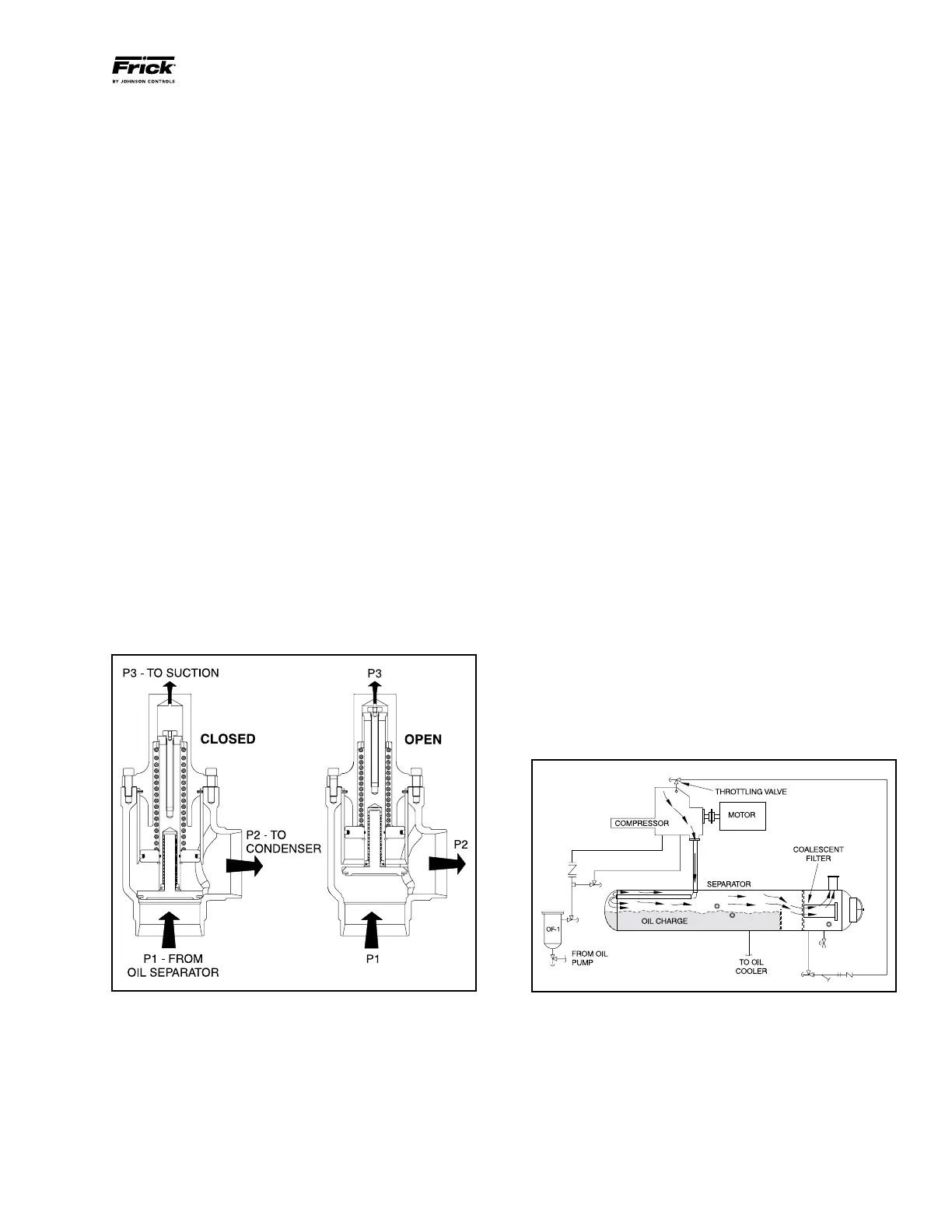
Once the compressor is running it will begin to force gas to
the condenser at connection P2. As the condenser heats up
it will begin to rise in pressure as the compressor suction
pulls down in pressure. As soon as differential pressure is
developed between the condenser and suction, these pres‑
sures act across a piston inside the cold‑start valve to partially
overcome the spring force. When the differential pressure
reaches and exceeds 30 psi, the piston fully overcomes the
spring force and powers the valve fully open for very low
operating pressure drop.
For booster applications, the valve is equipped with a lighter
spring which produces 15 psi oil pressure above suction
pressure before it fully powers open.
The RWB II package is also equipped with a suction check
valve bypass. The oil separator will slowly bleed down to
system suction pressure when the unit is stopped. This allows
the compressor drive motor to have an easier start, and the
discharge check valve will seat more tightly. See the "SUC‑
TION CHECK VALVE BYPASS" section for operation.
NOTE: For alarm descriptions and shutdown or cutout
parameters, see publication S90-010 O.
COLD START VALVE
DEMAND PUMP OIL SYSTEM
This system is designed to provide adequate compressor
lubrication for some high stage applications that operate with
low differential pressure across the compressor suction and
discharge and all booster applications.
During the period from start‑up to normal operation the oil
pressure alarm and oil pressure cutout setpoints will vary
according to formulas built into the microprocessor control
program.
NOTE: For alarm descriptions and shutdown or cutout
parameters, see publication S90-010 O.
COMPRESSOR OIL SEPARATION SYSTEM
The RWB II is an oil flooded screw compressor. Most of the
oil discharged by the compressor separates from the gas flow
in the oil charge reservoir. Some oil, however, is discharged
as a mist which does not separate readily from the gas flow
and is carried past the oil charge reser voir. One or more
coalescer filter elements then COALESCE the oil mist into
droplets which fall to the bottom of the coalescer section of
the oil separator. The return of this oil to the compressor is
controlled by a throttling valve on both high stage and booster
applications (see Figure 19).
NOTE: Open throttling valve only enough to keep co-
alescer end of separator free of oil.
The sight glass located near the bottom of the coales cer sec‑
tion of the oil separator should remain empty during normal
operation. If an oil level develops and remains in the sight
glass, a problem in the oil return separation system or com‑
pressor operation has developed. Refer to MAINTENANCE
for information on how to correct the prob lem.
NOTE: Normal operating level is midway between the
top sight glass and bottom sight glass.
OIL SEPARATION SYSTEM
Figure 18
Figure 19