RWB II ROTARY SCREW COMPRESSOR UNITS
GENERAL INFORMATION
070.200-IOM (DEC 11)
Page 3
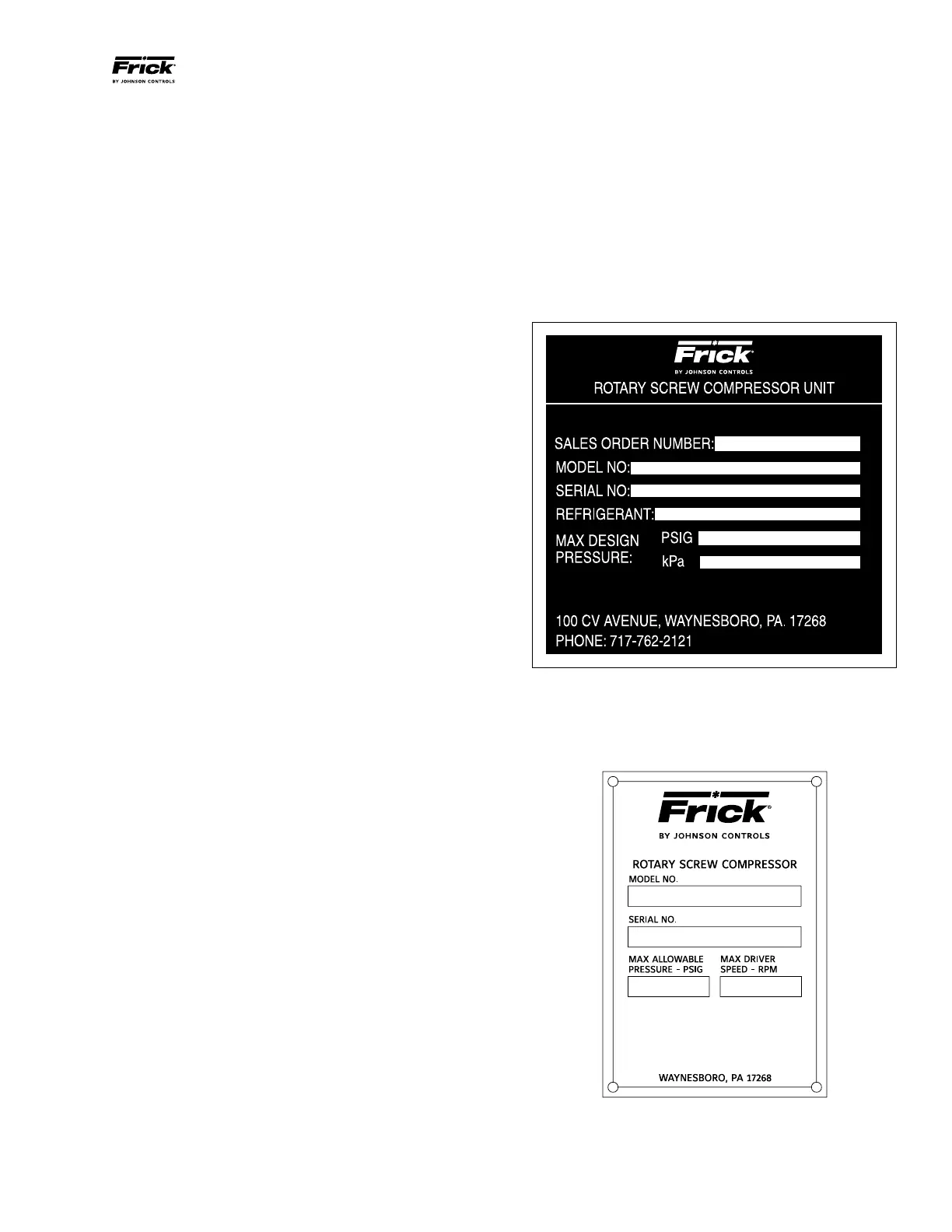
COMPRESSOR IDENTIFICATION
Each compressor has an identification data plate (see below),
containing compressor model and serial number mounted on
the compressor body.
COMPRESSOR DATA PLATE
COMPRESSOR and UNIT IDENTIFICATION
Each compressor unit has 2 identifica tion data plates. The
compressor data plate containing compressor model and
serial number is mounted on the compressor body. The unit
data plate containing unit model, serial number and Frick
®
sales order number is mounted on the side of the Quantum
control panel.
NOTE: When inquiring about the compres sor or unit,
or ordering repair parts, provide the MODEL, SERIAL,
and FRICK
®
SALES ORDER NUMBERS from these data
plates.
PREFACE
This manual has been prepared to acquaint the owner and
serviceman with the INSTALLATION, OPERATION, and
MAIN TEN ANCE procedures recommended for Frick
®
RWB II
Rotary Screw Compres sor Units.
For information about the functions of the electrical control
panel, communications, specifications, and wiring diagrams,
see S90‑010 O, S90‑010 M, and 090‑010 CS for the Quan‑
tum panel.
It is most important that these units be properly applied to an
adequately controlled refrigeration system. Your authori zed
Frick representative should be con sulted for expert guidance
in this determination.
Proper performance and continued satisfaction with these
units is dependent upon:
CORRECT INSTALLATION
PROPER OPERATION
REGULAR, SYSTEMATIC MAINTENANCE
To ensure correct installation and application, the equip ment
must be properly selected and connected to a properly de‑
signed and installed system. The Engi neering plans, piping
layouts, etc. must be detailed in accor dance with the best
practices and local codes, such as those outlined in ASHRAE
literature.
A refrigeration compressor is a VAPOR PUMP. To be certain
that it is not being subjected to liquid refriger ant carryover it
is necessary that refriger ant controls are carefully selected
and in good operating condition; the piping is properly sized
and traps, if necessary, are correct ly arranged; the suction
line has an accumulator or slugging protec tion; that load
surges are known and provisions made for control; operating
cycles and de frost ing periods are reasonable; and that high
side condensers are sized within system and compressor
design limits.
It is recommended that the entering vapor temperature to the
compressor be superheated to 10°F above the refriger ant
saturation temperature. This assures that all refrigerant at
the compressor suction is in the vapor state.
DESIGN LIMITATIONS
The compressor units are designed for operation within
the pressure and temperature limits as shown in Frick Pub.
070.200‑SED.
JOB INSPECTION
Immediately upon arrival examine all crates, boxes and
exposed compressor and com ponent surfaces for dam age.
Unpack all items and check against shipping lists for any
possible shortage. Examine all items for damage in transit.
TRANSIT DAMAGE CLAIMS
All claims must be made by consignee. This is an ICC require‑
ment. Request immediate inspection by the agent of the carrier
and be sure the proper claim forms are execut ed.
Report damage or shortage claims im mediately to Johnson
Controls Inc.,Frick Sales Ad ministration Depart ment, in
Waynes boro, PA.