RWB II ROTARY SCREW COMPRESSOR UNITS
INSTALLATION
070.200-IOM (DEC 11)
Page 16
Motor starter and interlock wiring require ments are shown
in the Starter Wiring Diagram. All of the equipment shown
is supplied by the installer unless a starter package is pur‑
chased separately from Frick. Starter packages should
consist of:
1. The compressor motor starter of the specified HP and
voltage for the starting method specified (across‑the‑line,
autotransformer, wye‑delta, or solid‑state).
NOTE: If starting methods other than across-the-line are
desired, a motor/compressor torque analysis must be
done to ensure that sufficient starting torque is avail able,
particularly in booster applica tions. Contact Johnson
Controls-Frick if assistance is required.
2. If specified, the starter package can be supplied as a
combination starter with circuit breaker disconnect. Howev er,
the motor overcurrent protection/disconnection device can
be applied by others, usually as a part of an electrical power
distribution board.
3. The oil pump starter with fuses, or in the case where the
compressor motor is a different voltage from the oil pump
motor, with a circuit breaker disconnect suitable for sepa rate
power feed.
4. A 2.0 KVA control power transformer (CPT) to supply 120
volt control power to the microprocessor control system and
separator oil heaters is included. If environ mental condi tions
require more than the usual two 500 watt oil heaters, an ap‑
propriately oversized control transformer will be required. If
frequent power fluc tuations are anticipat ed or extremely noisy
power lines are encoun tered, a regulating control transformer
should be considered. Contact Johnson Controls‑Frick for
assistance.
5. For customer‑supplied across‑the‑line starters, a shunt‑
ing device must be installed across the Current Transformer
(terminals 3 & 4).
If the shunting device is not in-
stalled, the Analog I/O board on the
Quantum panel may be severly
damaged at start-up (see Starter Wiring Diagram,
Figure 15).
6. One each normally open compressor motor and oil pump
motor starter auxiliary contact should be supplied. In addi‑
tion to the compressor and oil pump motor starter coils, the
CT and CPT secondaries should be wired as shown on the
starter package wiring diagram. The load on the control panel
for the compressor motor starter coil should not exceed a
Nema size 3 starter. For larger starters, an interposing relay
must be used to switch the compres sor motor starter coil(s).
NOTE: Do not install a compressor HAND/OFF/AUTO
switch in the starter package as this would bypass the
compressor safety devices.
7. The compressor motor Current Transformer (CT) is in‑
stalled on any one phase of the compressor leads.
NOTE: The CT must see all the current of any one phase,
therefore in wye-delta applications BOTH leads of any
one phase must pass through the CT.
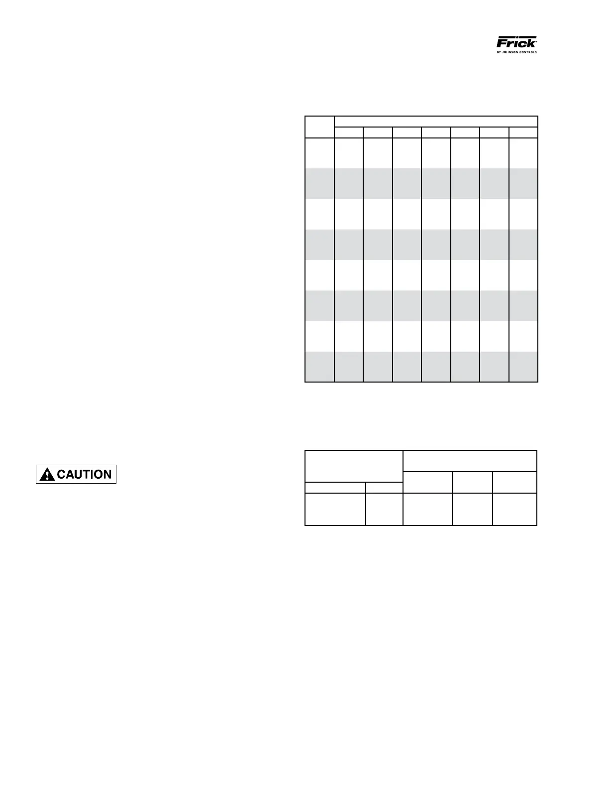
CURRENT TRANSFORMER (CT) RATIOS
The CT ratio for various motor sizes (with a 5 amp second‑
ary) is given in the following table:
VOLTAGE
HP 200 230 380 460 575 2300 4160
20 100:5 100:5 50:5 50:5 50:5 ‑ ‑
25 100:5 100:5 50:5 50:5 50:5 ‑ ‑
30 200:5 100:5 100:5 50:5 50:5 ‑ ‑
40 200:5 200:5 100:5 100:5 50:5 ‑ ‑
50 200:5 200:5 100:5 100:5 100:5 ‑ ‑
60 300:5 200:5 200:5 100:5 100:5 ‑ ‑
75 300:5 300:5 200:5 200:5 100:5 ‑ ‑
100 400:5 300:5 200:5 200:5 200:5 ‑ ‑
125 500:5 400:5 300:5 200:5 200:5 ‑ ‑
150 600:5 500:5 300:5 300:5 200:5 ‑ ‑
200 800:5 600:5 400:5 300:5 300:5 100:5 50:5
250 800:5 800:5 500:5 400:5 300:5 100:5 50:5
300 1000:5 1000:5 600:5 500:5 400:5 100:5 50:5
350 ‑ 1000:5 800:5 500:5 500:5 100:5 100:5
400 ‑ ‑ 800:5 600:5 500:5 200:5 100:5
450 ‑ ‑ 1000:5 800:5 600:5 200:5 100:5
500 ‑ ‑ 1000:5 800:5 600:5 200:5 100:5
600 ‑ ‑ 1200:5 1000:5 800:5 200:5 100:5
700 ‑ ‑ ‑ 1200:5 1000:5 200:5 200:5
800 ‑ ‑ ‑ ‑ 1000:5 300:5 200:5
900 ‑ ‑ ‑ ‑ 1200:5 300:5 200:5
1000 ‑ ‑ ‑ ‑ ‑ 300:5 200:5
1250 ‑ ‑ ‑ ‑ ‑ 400:5 200:5
1500 ‑ ‑ ‑ ‑ ‑ 500:5 300:5
MINI MUM BURDEN RATINGS
The following table gives the minimum CT burden ratings.
This is a function of the distance between the motor starting
package and the compressor unit.
MAXIMUM DISTANCE FROM
BURDEN
FRICK PANEL
RATING
USING # USING # USING #
ANSI VA 14 AWG 12 AWG 10 AWG
B‑0.1 2.5 15 ft 25 ft 40 ft
B‑0.2 5 35 ft 55 ft 88 ft
B‑0.5 12.5 93 ft 148 ft 236 ft