RWB II ROTARY SCREW COMPRESSOR UNITS
MAINTENANCE
070.200-IOM (DEC 11)
Page 36
5. Isolate the oil pressure transducer PE‑1 from the package
and open it to atmosphere.
6. Measure the voltage of PE‑1 on connector P4 (terminals
WHT and BLK) on the SBC.
7. The voltage reading should be between 1.1 VDC and 1.29
VDC at standard atmospheric pressure. PE‑1, PE‑2, and PE‑
3 all have a span of 300 PSI as compared to PE‑4 with a span
of 100 PSI. Therefore, atmospheric pressure changes have a
lesser effect which is 0.0067 VDC per 1000 feet of elevation
and 0.00067 VDC per 0.1 inch Hg barometric deviation.
8. Isolate transducer PE‑2 from the package and depres‑
surize. NOTE: Recover or transfer all refrigerant vapor,
in accordance with local ordinances, before opening to
atmosphere.
9. Measure the voltage of PE‑2 on connector P4 (terminals
WHT and BLK) on the SBC.
10. The voltage reading should be between 1.1 VDC and 1.29
VDC at standard atmospheric pressure (see Step 12).
11. Since the discharge pressure, PE‑3, cannot be closed
off from its sensing point (code require ments), close all
transducers from atmosphere and open them to their sens‑
ing points so all transducers can equalize to separator
pressure.
12. Measure the voltage of PE‑3 on connector P4 (terminals
WHT and BLK) on the SBC.
13. Measure the voltage of PE‑1 on connector P4 (terminals
WHT and BLK) on the SBC.
14. These two voltages should be within .04 VDC of one
another.
15. Test is complete.
PRESSURE TRANSDUCERS - REPLACEMENT
1. Shut off control power.
2. Close the applicable transducer isolation valve. NOTE:
To change the discharge pressure transducer (PE-3),
it will be necessary to depressurize the entire com-
pressor package. Follow "General Instructions For
Replacing Compressor Unit Components" before going
to step 3.
3. Open the microprocessor control panel.
4. Use the chart to identify transducer terminals of the Analog
Board (Quantum panel) or SBC Board (Plus panel).
MANIFOLD
TRANSDUCER CONNECTION
Oil Pressure PE‑1
Oil Before Filter (PSID) * PE‑2
Discharge Pressure PE‑3
Suction Pressure PE‑4
* Used for Full and Cycling pumps and ext. oil cooler.
5. Disconnect transducer leads by loosening the terminal
screws for the transducer to be changed.
6. Tape a 3 ft. length of pull wire to the leads of the trans du‑
cer to be removed.
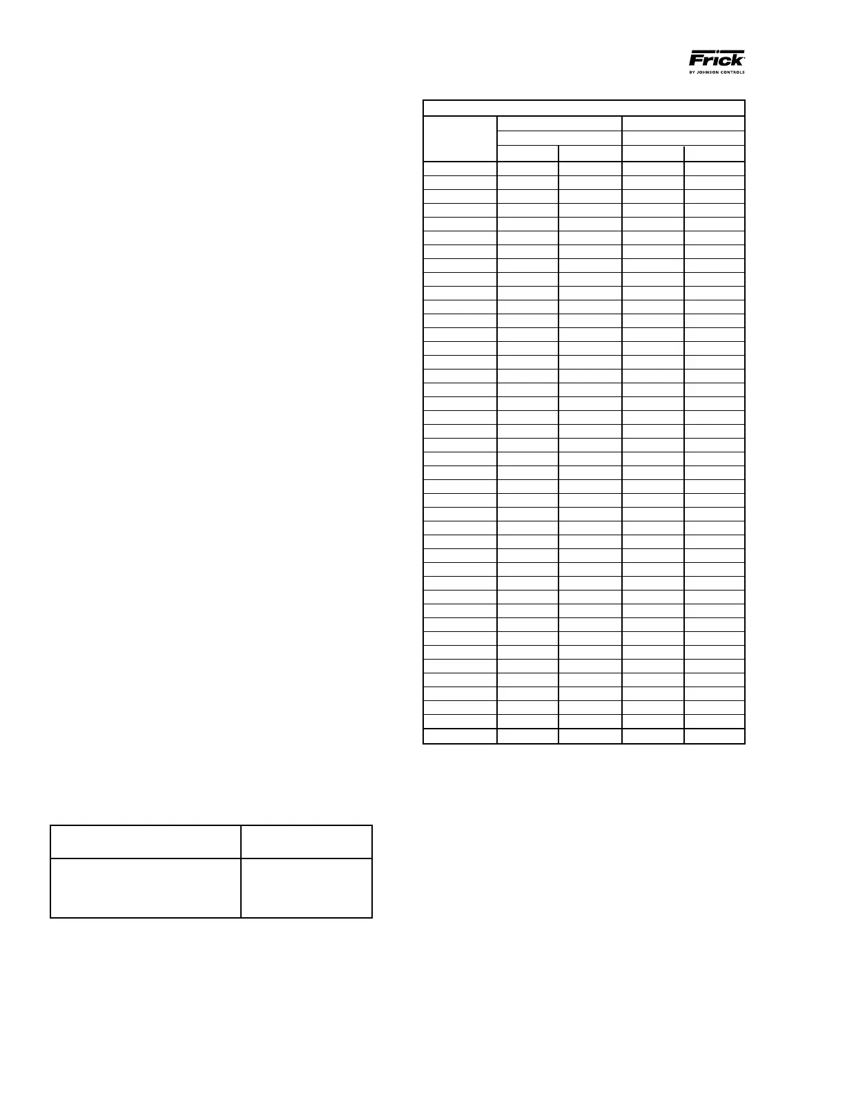
* Below 0 PSIG measured in inches of mercury.
PRESSURE TRANSDUCER CONVERSION DATA
200 psi 500 psi
Sensor Range - PSI Range - PSIG*
Voltage low high low high
1.0 29.92" 9.57" 29.92" 4.10
1.1 29.92" 0.30 29.92" 16.60
1.2 29.92" 5.30 17.10" 29.10
1.3 19.74" 10.30 4.10 41.60
1.4 9.57" 15.30 16.60 54.10
1.5 0.30 20.30 29.10 66.60
1.6 5.30 25.30 41.60 79.10
1.7 10.30 30.30 54.10 91.60
1.8 15.30 35.30 66.60 104.10
1.9 20.30 40.30 79.10 116.60
2.0 25.30 45.30 91.60 129.10
2.1 30.30 50.30 104.10 141.60
2.2 35.30 55.30 116.60 154.10
2.3 40.30 60.30 129.10 166.60
2.4 45.30 65.30 141.60 179.10
2.5 50.30 70.30 154.10 191.60
2.6 55.30 75.30 166.60 204.10
2.7 60.30 80.30 179.10 216.60
2.8 65.30 85.30 191.60 229.10
2.9 70.30 90.30 204.10 241.60
3.0 75.30 95.30 216.60 254.10
3.1 80.30 100.30 229.10 266.60
3.2 85.30 105.30 241.60 279.10
3.3 90.30 110.30 254.10 291.60
3.4 95.30 115.30 266.60 304.10
3.5 100.30 120.30 279.10 316.60
3.6 105.30 125.30 291.60 329.10
3.7 110.30 130.30 304.10 341.60
3.8 115.30 135.30 316.60 354.10
3.9 120.30 140.30 329.10 366.60
4.0 125.30 145.30 341.60 379.10
4.1 130.30 150.30 354.10 391.60
4.2 135.30 155.30 366.60 404.10
4.3 140.30 160.30 379.10 416.60
4.4 145.30 165.30 391.60 429.10
4.5 150.30 170.30 404.10 441.60
4.6 155.30 175.30 416.60 454.10
4.7 160.30 180.30 429.10 466.60
4.8 165.30 185.30 441.60 479.10
4.9 170.30 190.30 454.10 491.60
5.0 175.30 195.30 466.60 504.10
At 0 psig 1.094 V 1.494 V 0.968 V 1.268 V
7. Pull the transducer leads through the conduit until pull wire
extends out of the conduit hole in the transducer manifold.
Separate the transducer leads from the pull wire.
8. Unscrew the transducer using a wrench on the metal hex at
the base of the transducer. DO NOT ATTEMPT TO LOOSEN
OR TIGHTEN TRANSDUCERS BY THEIR TOP CASING.
9. Install new transducer and tape leads to the pull wire.
10. Pull new transducer leads into the control panel and re‑
connect them to the terminal strip. See Analog Board layouts
in S90‑010 M (Quantum panel) .
11. Close the microprocessor control panel.
12. Reopen the transducer isolation valve.
13. Turn on control power.