RWB II ROTARY SCREW COMPRESSOR UNITS
OPERATION
070.200-IOM (DEC 11)
Page 20
COMPRESSOR HYDRAULIC SYSTEM
The compressor hydraulic system moves the movable slide
valve (MSV) to load and unload the compressor. It also moves
the movable slide stop (MSS) to increase or decrease the
compressor’s volume ratio (Vi).
The hydraulic cylinder located at the inlet end of the TDS
compressor serves a dual purpose. It is separated by a fixed
bulkhead into two sections. The movable slide valve (MSV)
sec tion is to the left of the bulkhead and the movable slide
stop (MSS) to the right. Both sections are considered double
acting hydraulic cylinders as oil pressure moves the pistons
in either direction.
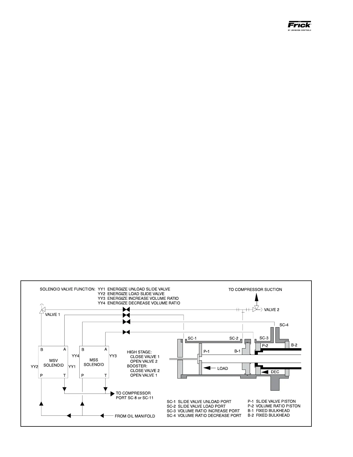
Both sections are controlled by double‑acting, four‑way
solenoid valves which are actuated when a signal from the
appropriate micropro cessor output energizes the solenoid
valve.
Compressor Loading: The compressor loads when MSV
solenoid YY2 is energized and oil flows from the oil manifold
through valve ports P and B to cylinder port SC‑2 and enters
the load side of the cylinder. Simultaneously, oil con tained in
the unload side of the cylinder flows out cylinder port SC‑1
through valve ports A and T to com pressor closed thread
port.
Compressor Unloading: The compressor un loads when
MSV solenoid YY1 is energized and oil flows from the oil
manifold through valve ports P and A to cylinder port SC‑1
and enters the unload side of the cylinder. Simultaneous ly,
oil contained in the load side of the cylinder flows out com‑
pressor port SC‑2 through valve ports B and T to com pressor
closed thread port.
Figure 20
NOTE: High Stage Operation: An alternative piping ar-
rangement has been provided to increase slide valve
response time during high stage operation.
Higher operating pressures will slow the com pressor un‑
loading response time. Unloading response time can be
increased by closing valve 1 (oil manifold pressure) and
opening valve 2 to compressor suction pressure. See Figure
20. NEVER OPEN VALVE 1 AND VALVE 2 AT THE SAME
TIME DURING COMPRESSOR OPERATION.
VOLUMIZER VOLUME RATIO CONTROL
Vi Increase
The volume ratio Vi is increased when MSS solenoid YY3
is energized and oil flows from the oil manifold through
valve ports P and A to cylinder port SC‑3 and enters the
increase side of the cylinder. Simul taneous ly, oil contained
in the decrease side of the cylinder flows out cylinder port
SC‑4 through valve ports B and T to compressor closed
thread port.
Vi Decrease
The volume ratio Vi is decreased when MSS solenoid YY4
is ener gized and oil flows from the oil manifold through
valve ports P and B to cylinder port SC‑4 and enters the
decrease side of the cylinder. Simul taneous ly, oil contained
in the increase side of the cylinder flows out cylinder port
SC‑3 through valve ports A and T to compressor closed
thread port.
MSV and MSS HYDRAULIC CYLINDER and SOLENOID VALVES