RWB II ROTARY SCREW COMPRESSOR UNITS
INSTALLATION
070.200-IOM (DEC 11)
Page 8
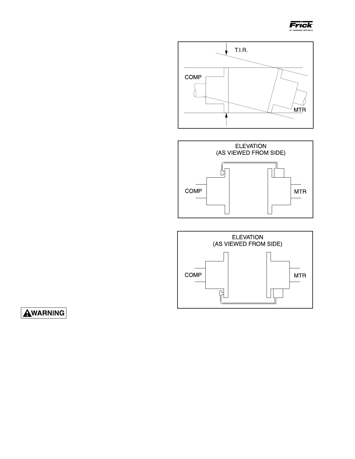
Figure 1 - Angular Misalignment
Figure 2 - Dial Indicator Attached (at 12 o'clock)
Figure 3 - Dial Indicator at 6 o'clock
3. Reassemble the coupling with the disc packs and the cen‑
ter spool. Center the coupling between the shafts and ensure
that the keys are fully engaged in their keyways. Ensure that
they are reassembled exactly as they were disassembled.
Torque disc pack hardware to specification in BP Series
Coupling Data Table.
4. Key and secure the hubs to the shafts by tightening the
clamping bolts. Make sure that the keyways are offset 180°
to maintain balance.
5. Torque the clamping bolts of both hubs to the torque value
given in the Data Table. DO NOT USE ANY LUBRICANT
ON THESE BOLTS.
6. IMPORTANT: Only after the shaft clamping bolts are
tightened to their final torque can the keyway setscrew be
tightened! If the keyway setscrew is tightened before the shaft
clamping bolts are tightened, then the hub can be cocked
on the shaft.
7. Proceed to Coupling Alignment.
COUPLING ALIGNMENT PROCEDURE
The life of the compressor shaft seal and bearings, as well
as the life of the motor bearings, is dependent upon proper
coupling alignment. Couplings may be aligned at the factory
but realignment MUST ALWAYS be done on the job site
after the unit is securely mounted on its founda tion. Initial
alignment must be made prior to start‑up and rechecked
after a few hours of operation. Final (HOT) field alignment
can only be made when the unit is at operating tempera ture.
After final (HOT) alignment has been made and found to be
satisfac tory for approximately one week, the motor may be
dowelled to maintain align ment.
NOTE: Frick recommends cold aligning the motor .005"
high. This cold misalignment compensates for thermal
growth when the unit is at operating temperature.
The following procedure is applicable to both the CH and
DBZ‑B couplings. Dial indicators are to be used to measu‑
re the angular and parallel shaft misalign ment. Coupling
alignment is attained by alternately measuring angular and
parallel misalignment and repositioning the motor until the
misalignment is within specified tolerances.
ALWAYS LOCK OUT MAIN MOTOR
DISCONNECT BEFORE TOUCHING
MOTOR SHAFT. MISALIGNMENT
MUST NOT EXCEED .004" FOR ALL CH, DBZ-B AND
SERIES 52 COUPLINGS EXCEPT DBZ-B 226 WHICH
SHALL NOT EXCEED .003".
ANGULAR ALIGNMENT
1. To check angular alignment, as shown in Figure 1., attach
dial indicator rigidly to the motor hub. Move indicator stem
so it is in contact with the outside face of compressor hub,
as shown in Figure 2.
NOTE: When DBZ-B couplings are used on motors
with sleeve bearings, it is necessary to secure the two
coupling hubs with a bolt to prevent them from drifting
apart when rotating.
2. Rotate both coupling hubs several revolutions until they
seek their normal axial positions.
Check the dial indicator to be sure that the indicator stem is
slightly loaded so as to allow movement in both direc tions.
3. Set the dial indicator at zero when viewed at the 12 o’clock
position, as shown in Figure 2.
4. Rotate both coupling hubs together 180° (6 o’clock po‑
sition), as shown in Figure 3. At this position the dial indicator
will show TOTAL angular misalignment.
NOTE: The use of a mirror is helpful in reading the indi-
cator dial as coupling hubs are rotated.
5. Loosen motor anchor bolts and move or shim motor to
correct the angular misalignment.
After adjustments have been made for angular mis align ment
retighten anchor bolts to prevent inac curate read ings. Repeat
Steps 3 through 5 to check corrections. Further adjustments
and checks shall be made for angular misalignment until the
total in dicator reading is within the specified tolerance.