RWB II ROTARY SCREW COMPRESSOR UNITS
OPERATION
070.200-IOM (DEC 11)
Page 18
Operation
OPERATION and START-UP INSTRUCTIONS
The Frick RWB II Rotary Screw Compressor Unit is an inte‑
grated system consisting of six major subsystems:
1. Control Panel (See publication S90‑010 O, S90‑010 M, &
090‑010 CS).
2. Compressor
3. Compressor Lubrication System
4. Compressor Oil Separation System
5. Compressor Hydraulic System
6. Compressor Oil Cooling System
7. Compressor Easy‑Start System
The information in this section of the manual provides the
logical step‑by‑step instructions to properly start up and
operate the RWB II Rotary Screw Compressor Unit.
The following subsections must be read and understood
before attempting to start or operate the unit.
TDSH COMPRESSOR
The Frick RWB II rotary screw compressor utilizes mating
asymmetrical profile helical rotors to provide a continuous
flow of refriger ant vapor and is designed for both high pres‑
sure and low pressure applica tions. The compressor incorpor‑
ates the following features:
1. High capacity roller bearings to carry radial loads at both
the inlet and outlet ends of the compres sor.
2. Heavy‑duty, four‑point angular contact ball bearings
to carry axial loads are mounted at the discharge end of
compressor.
3. Balance pistons located in the inlet end of the compres sor
to reduce axial loads on the axial load bearings and increase
bearing life.
4. Moveable slide valve to provide infinite step capacity
control from 100 to 10%.
5. VOLUMIZER volume ratio control to allow infinite ly variable
volume ratio from 2.2 to 5.0 during compres sor operation for
all models except 480 which is 2.2 to 4.2.
6. A hydraulic unloader cylinder to operate the slide stop
and slide valve.
7. Bearing and casing design for 350 PSI discharge pressure.
This PSI rating applies only to the compressor and does
not reflect the design pressure of the various system
components.
8. All bearing and control oil vented to closed thread in the
compressor instead of suction port to avoid performance
penalties from superheating suction gas.
9. Shaft seal design to maintain operating pressure on seal
well below discharge pressure, for increased seal life.
10. Oil injected into the rotors to maintain good volumetric and
adiabatic efficiency even at very high compression ratios.
11. Shaft rotation clockwise facing compressor, suitable for
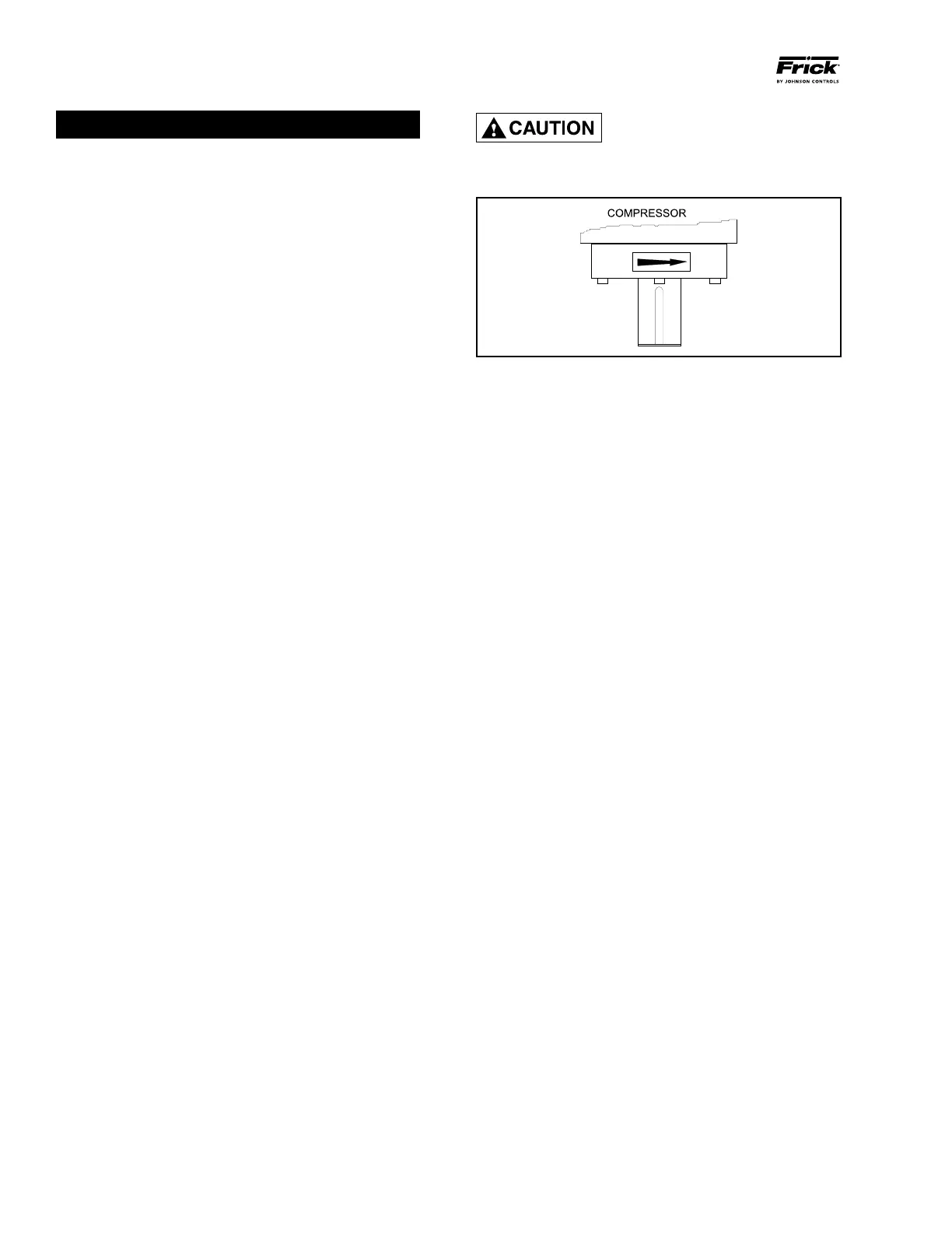
all types of drives. SEE CAUTION.
12. Dual compressor casing design for very low airborne
noise transmission.
COM P R E SSO R ROTAT ION I S
CLOCKWISE WHEN FACING THE
COMPRESSOR DRIVE SHAFT. THE
COMPRESSOR SHOULD NEVER BE OPERATED IN RE-
VERSE ROTATION AS BEARING DAMAGE WILL RESULT.
Figure 17
COMPRESSOR LUBRICATION SYSTEM
The lubrication system on an RWB II screw com pres sor unit
performs several functions:
1. Provides lubrication to bearings and seal.
2. Provides a cushion between the rotors to minimize noise
and vibrations.
3. Helps keep the compressor cool and prevents
overheat ing.
4. Provides an oil supply to hydraulically actuate the slide
valve and slide stop.
5. Provides oil pressure to the balance pistons to help in‑
crease bearing life.
6. Provides an oil seal between the rotors to prevent rotor
contact or gas bypassing.
The compressor unit may be equipped with either a no
pump or a demand pump lubrication system. Additionally,
either system may contain dual oil filters and liquid injection,
water‑cooled, or thermosyphon oil cooler for compressor
oil cooling.
NO PUMP OIL SYSTEM
The RWB II screw compressor unit is designed to be self‑lu‑
bricating. Oil being supplied to the compres sor from the oil
separator is at system head pressure. Within the compressor,
oil porting to all parts of the compressor is vented back to a
point in the compres sor’s body that is at a pressure lower than
compressor discharge pressure. The compressor’s normal
operation makes the compressor unit operate essentially as
its own oil pump. All oil entering the compressor is moved by
the compressor rotors out the compressor outlet and back
to the oil separator.
For normal high‑stage operation an oil pump is not re‑
quired.
COLD-START SYSTEM
The RWB II package is equipped with a special "cold start"
discharge check valve on the gas outlet connection of the
oil separator (see Figure 18). This valve causes the oil sepa‑
rator to develop oil pressure rapidly on initial start in order to
lubricate the compressor without requiring an oil pump, even
in cold ambient temperatures with all pressures equalized.