RWB II ROTARY SCREW COMPRESSOR UNITS
INSTALLATION
070.200-IOM (DEC 11)
Page 13
ECONOMIZER - HIGH STAGE (OPTIONAL)
The economizer option provides an increase in system ca‑
pacity and efficiency by subcooling liquid from the condenser
through a heat exchanger or flash tank before it goes to the
evapora tor. The subcooling is provided by flashing liquid in
the economizer cooler to an intermediate pressure level.The
intermediate pressure is provided by a port located part way
down the compres sion process on the screw compressor.
As the screw compressor unloads, the economizer port will
drop in pressure level, eventually being fully open to suc‑
tion. Because of this, an output from the microproces sor
is generally used to turn off the supply of flashing liquid on
a shell and coil or DX economizer when the capacity falls
below approximately 45%‑60% capacity (85%‑90% slide
valve position). This is done because the compressor will
be more efficient operating at a higher slide valve position
with the economizer turned off, than it will at a low slide valve
position with the economizer turned on. Please note however
that shell and coil and DX economizers can be used at low
compressor capaciti es in cases where efficien cy is not as
important as assuring that the liquid supply is subcooled. In
such cases, the economi zer liquid solenoid can be left open
whenever the com pressor is running.
WATER-COOLED OIL COOLING (Optional)
The plate and shell type water‑cooled oil cooler is mounted
on the unit complete with all oil piping. The customer must
supply adequate water connections and install the two‑way
water regulating valve if ordered in lieu of a three‑way oil
temperature valve. It is recom mended (local codes permitting)
that the water regula tor be installed on the water outlet con‑
nection. Insert the water regulator valve bulb and well in the
chamber provided on the oil outlet connection. Determine
the size of the water‑cooled oil cooler supplied with the unit,
then refer to table for the water connec tion size. The water
supply must be sufficient to meet the required flow.
Frick recommends a closed‑loop system for the waterside
of the oil cooler. Careful attention to water treatment is es‑
sential to ensure adequate life of the cooler if cooling tower
water is used. It is imperative that the condition of cool-
ing water and closed-loop fluids be analyzed regularly
and as necessary and maintained at a pH of 7.4, but not
less than 6.0 for proper heat exchanger life. After initial
start‑up of the compressor package, the strainer at the inlet
of the oil cooler should be cleaned several times in the first
24 hours of operation.
* Based on 100 foot liquid line. For longer runs, increase line
size accordingly.
** For models 60 and 76, contact Frick engineering.
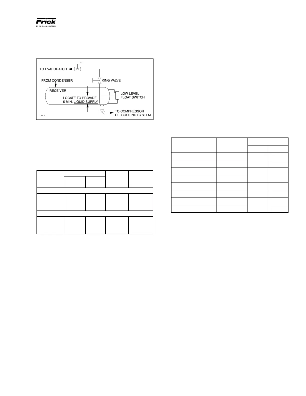
LIQUID LINE SIZES/RECEIVER VOLUME
Liquid line sizes and the additional receiver volume (quanti‑
ty of refrigerant required for 5 minutes of liquid injection oil
cooling) are given in the following table:
LIQUID LINE SIZE and RECEIVER VOLUME
The level‑control method utilizes a float level control on the
receiver to close a solenoid valve feeding the evaporator
when the liquid falls below that amount necessary for 5
minutes of liquid injection oil cooling. See Figure 10.
Figure 10
In some applications, the plate and shell oil cooler may be
subjected to severe water conditions, including high tem‑
perature and/or hard water conditions. This causes accel‑
erated scaling rates which will penalize the performance of
the heat exchanger. A chemical cleaning process will extend
the life of the Plate and Shell heat exchanger. It is important
to establish regular cleaning schedules.
Cleaning: A 3% solution of Phosphoric or Oxalic Acid is
recommended. Other cleaning solutions can be obtained from
your local distributor, but they must be suitable for stainless
steel. The oil cooler may be cleaned in place by back flushing
with recommended solution for approximately 30 minutes.
After back flushing, rinse the heat exchanger with fresh water
to remove any remaining cleaning solution.
NOTE: The water-regulating valve shipped with the unit
will be sized to the specific flow for the unit.
OIL COOLER DATA TABLE
RWB II TYPICAL
CONNECTION
MODEL COOLER INLET OUTLET
60 ‑ 134 High Stage 116 Plates 3" 3"
100 ‑ 270 Booster 66 Plates 2" 2"
177/222 High Stage 190 Plates 3" 3"
270 High Stage 288 Plates 3" 4"
316/399 Booster 56 Plates 3" 3"
316/399 High Stage 136 Plates 4" 5"
480 Booster 72 Plates 3" 3"
480 High Stage 188 Plates 4" 5"
LINE SIZE* POUND LIQUID
RWB II
SCH 80 OD
PER VOLUME
MODEL ** PIPE TUBING 5 MIN. CU FT
R-717 HIGH STAGE*
100‑134 3/4 – 80 2.0
177‑270 1 – 140 4.0
316‑480 1¼ – 250 7.0
R-717 BOOSTER*
100‑134 1/2 – 20 0.5
177‑270 3/4 – 30 1.0
316‑480 1 – 40 1.5