RWB II ROTARY SCREW COMPRESSOR UNITS
INSTALLATION
070.200-IOM (DEC 11)
Page 15
ECONOMIZER LOAD BALANCING
The most energy efficient manner to operate an economizer
system, when using multiple compressors on a common
economizer vessel, is to take as much of the flash gas as
possible to the compressors that are fully loaded. This can
be done in at least two ways.
1. Use the economizer output from the microprocessor to
turn off a solenoid, or to actuate the electric shutoff option
on a back‑pressure regulator, based on percent of slide valve
travel. This will direct all the flash vapor to the other loaded
compressors.
2. A dual‑setpoint back‑pressure regulator valve can be used
in each of the individual economizer vapor lines. When a com‑
pressor is running near full load, the BPR valve will operate
on the desired setpoint, or basically wide open, to minimize
pressure drop in the line. When one compressor unloads
below the slide valve position where the economizer output
on the microprocessor turns on, the dual‑setpoint feature of
the regulator can be actuated by this output to control the
pressure, on the vessel side of the regulator, to be a few psi
higher. Consequently, the flash gas will be sent to the loaded
compressors first, until they can’t handle all the vapor and
the pressure in the vessel starts to rise. Then, some of the
vapor will go to the unloaded compressor to help maintain
the vessel at the desired pressure. An example of a back‑
pressure regulator with electric shutoff and the dual‑setpoint
feature is an R/S A4ADS.
ELECTRICAL
NOTE: Before proceeding with electrical installation,
read the instructions in the section “Proper Installation
of Elec tronic Equip ment in an Industrial Environment”.
RWB II units are supplied with a QUANTUM control system.
Care must be taken that the controls are not exposed to
physical damage during handling, storage, and installa tion.
The single‑box control door must be kept tightly closed to
prevent moisture and foreign mat ter from entry.
NOTE: All customer connections are made in the single-
box control mounted on the oil separator. This is the
ONLY electrical enclosure and it should be kept tightly
closed whenever work is not being done in it.
VOLTAGE PROTECTION
Johnson Controls‑Frick does not advise nor support the use
of UPS power systems in front of the Quantum panel. With
a UPS power system providing shutdown protection for the
Quantum, the panel may not see the loss of the 3‑phase volt‑
age on the motor because the UPS could prevent the motor
starter contactor from dropping out. With the starter contactor
still energized, the compressor auxiliary will continue to feed
an “Okay” signal to the panel. This will allow the motor to be
subjected to a fault condition on the 3‑phase bus. Some fault
scenarios are:
1. The 3‑phase bus has power “on” and “off” in a continuous
cyclic manner which may cause the motor to overheat
due to repeated excessive in‑rush currents.
2. Motor cycling may damage the coupling or cause other
mechanical damage due to the repeated high torque
motor “bumps”.
3. Prolonged low voltage may cause the motor to stall and
overheat before the motor contactor is manually turned
off.
Under normal conditions, the loss of 3‑phase power will
shut the Quantum panel down, and it will restart upon power
return. If the panel was in:
• Auto – Compressor motor will return to running as
programmed.
• Remote – The external controller would reinitialize the
panel and proceed to run as required.
• Manual – The compressor will have to be restarted
manually after the 3‑phase bus fault has been cleared.
If the local power distribution system is unstable or prone
to problems, there are other recommendations to satisfy
these problems. If power spikes or low or high line voltages
are the problem, then Johnson Controls‑Frick
®
recommends
the use of a Sola
®
constant voltage (CV) transformer with
a line suppression feature. If a phase loss occurs, then you
will typically get a high motor amp shutdown. If problems
continue to exist, then an examination of the plant’s power
factor may be in order.
Unless careful design failure analysis is considered in the
implementation of power systems, the alternative solutions
provide a safer and less expensive implementation. In either
case, only one Sola
®
may be used per compressor. Each
compressor needs to be individually isolated from each other
through a dedicated control transformer. Sharing a common
control power source is an invitation for ground loops and
the subsequent unexplainable problems.
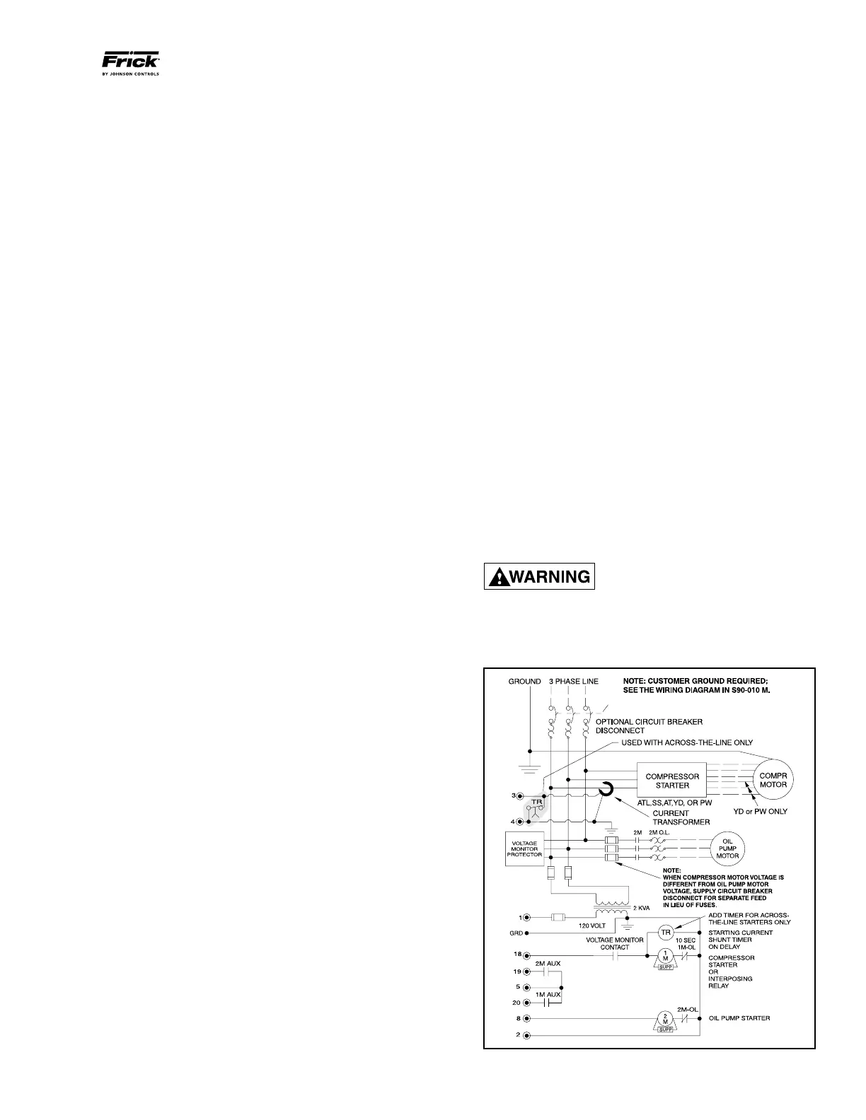
MOTOR STARTER PACKAGE
SBC Board damage may occur
without timer relay installed in con-
trol panel as shown in Starter Wir-
ing Diagram, Figure 15. All Frick motor starter packages
have the timer relay as standard.
STARTER WIRING DIAGRAM
Figure 15