RWB II ROTARY SCREW COMPRESSOR UNITS
MAINTENANCE
070.200-IOM (DEC 11)
Page 29
12. Open the suction and discharge service valves, and
also the liquid injection and economizer service valves, if
applicable.
13. Close the disconnect switch for the compressor motor
starter.
14. Start the unit.
DEMAND PUMP DISASSEMBLY
BEFORE OPENING ANY VIKING
PUMP LIQUID CHAMBER (PUMP-
ING CHAMBER, RESERVOIR, JACK-
ET, ETC.) ENSURE:
1. THAT ANY PRESSURE IN THE CHAMBER HAS BEEN
COMPLETELY VENTED THROUGH SUCTION OR DIS-
CHARGE LINES OR OTHER APPROPRIATE OPENINGS
OR CONNECTIONS.
2. THAT THE DRIVING MEANS (MOTOR, TURBINE,
ENGINE, ETC.) HAS BEEN “LOCKED OUT” OR MADE
NON OPERATIONAL SO THAT IT CANNOT BE STARTED
WHILE WORK IS BEING DONE ON THE PUMP.
FAILURE TO FOLLOW ABOVE LISTED PRECAUTION-
ARY MEASURES MAY RESULT IN SERIOUS INJURY
OR DEATH.
1. Mark head and casing before disassembly to ensure
proper reassembly. Position the idler pin, which is offset in
the pump head, up and equal distance between port con‑
nections to allow for proper flow of liquid through the pump.
2. Remove the head capscrews.
3. Tilt top of head back when removing to prevent idler from
falling off idler pin.
4. Remove idler and bushing assembly. If idler bushing
needs replacing, see INSTALLATION OF CARBON GRAPH-
ITE BUSHINGS.
5. Insert a brass bar or piece of hardwood in the port open‑
ing and between rotor teeth to keep shaft from turning. Turn
the locknut counterclockwise and remove locknut. See Figure
25 or 26.
6. Loosen two setscrews in face of bearing housing and
turn thrust bearing assembly counterclockwise and remove
from casing. See Figure 25 or 26.
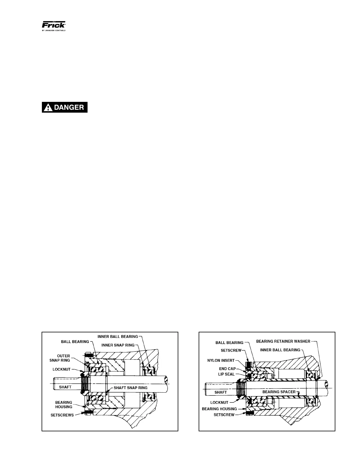
fFigure 25 - Thrust-Bearing assembly (GG, HJ, HL)
Figure 26 - Thrust-Bearing assembly (AS, AK, AL)
7. GG, HJ, HL: Remove snap ring from shaft. See Figure
25. AS, AK, AL: Remove bearing spacer from shaft. See
Figure 26.
8. Remove brass bar or piece of hardwood from port open‑
ing.
9.
The rotor and shaft can now be removed by tapping on end
of shaft with a lead hammer or, if using a regular hammer, use
a piece of hardwood between shaft and hammer. The rotary
member of the seal will come out with rotor and shaft.
10. AS, AK, AL: Remove bearing retainer washer. The
washer may have stayed with rotor and shaft when removed
or is against ball bearing. See Figure 26.
11. Remove the mechanical seal rotary member and spring
from rotor and shaft assembly.
12. GG, HJ, HL: Remove inner snap ring and single‑row ball
bearing from casing.
AS, AK, AL: Remove single‑row ball bearing from casing.
13. Remove seal seat or stationary part of seal from casing.
14. Disassemble thrust‑bearing assembly.
GG, HJ, HL: Remove outer snap ring from bearing hous ing
and remove ball bearing. See Figure 25.
AS, AK, AL: Loosen two set screws in flange outside di‑
ameter. Rotate end cap and lip seal counterclockwise and
remove. Remove ball bearing. See Figure 26.
The casing should be examined for wear, particularly in the
area between ports. All parts should be checked for wear
before pump is put together.
When making major repairs, such as replacing a rotor and
shaft, it is advisable to also install a new mechanical seal,
head and idler pin, idler, and bushing. See INSTALLATION
OF CARBON GRAPHITE BUSHINGS.
Clean all parts thoroughly and examine for wear or damage.
Check lip seals, ball bearings, bushing, and idler pin and
replace if necessary. Check all other parts for nicks, burrs,
excessive wear and replace if necessary.
Wash bearings in clean solvent and blow out with com‑
pressed air. Do not allow bearings to spin; turn them slowly
by hand. Spinning bearings will damage race and balls. Make
sure bearings are clean, then lubricate with refrigeration