RWB II ROTARY SCREW COMPRESSOR UNITS
INSTALLATION
070.200-IOM (DEC 11)
Page 10
HOT ALIGNMENT OF COMPRESSOR/MOTOR
Hot alignments can only be made after the unit has operated
for several hours and all components are at operating tem‑
peratures.
Shut down the unit and quickly affix dial indicator to coupling
motor hub, then take readings of both the face and rim of the
compressor hub. If these readings are within tolerance, record
reading, attach coupling guard and restart unit. However, if
the reading is not within limits, compare the hot reading with
the cold alignment and adjust for this difference; i.e. if the
rim at 0° and 180° readings indicates that the motor rises
.005" between its hot and cold state, .005" of shims should
be removed from under the motor.
After the initial hot alignment adjustment is made, restart unit
and bring to operating temperature. Shut down and recheck
hot alignment. Repeat procedure unit hot alignment is within
specified tolerance.
INSTALL COUPLING GUARD BE-
FORE OPERATING COMPRESSOR.
OIL PUMP COUPLING
Compressor units with direct motor/pump coupled pumps
need no pump/motor coupling alignment since this is main‑
tained by the close‑coupled arrangement.
HOLDING CHARGE AND STORAGE
Each RWB II compressor unit is pressure and leak tested at
the Frick factory and then thoroughly evacuated and charged
with dry nitrogen to ensure the integrity of the unit during
shipping and short term storage prior to installation.
NOTE: Care must be taken when entering the unit to
ensure that the nitrogen charge is safely released.
Holding charge shipping gauges on
separator and external oil cooler
are rated for 30 PSIG and are for
checking the shipping charge only. They must be re-
moved before pressure testing the system and before
charging the system with refrigerant. Failure to remove
these gauges may result in catastrophic failure of the
gauge and uncontrolled release of refrigerant resulting
in serious injury or death.
All units must be kept in a clean, dry location to prevent
corrosion damage. Reasonable consideration must be
given to proper care for the solid‑state components of the
microprocessor.
Unit which will be stored for more than two months must have
the nitrogen charge checked periodically.
COMPRESSOR UNIT OIL
DO NOT MIX OILS of different
brands, manufacturers, or types.
Mixing of oils may cause excessive
oil foaming, nuisance oil level cutouts, oil pressure loss,
gas or oil leakage and catastrophic compressor failure.
NOTE: The oil charge shipped with the unit is the best
suited lubricant for the conditions specified at the time
of purchase. If there is any doubt due to the refrigerant,
operating pressures, or temperatures, refer to Frick Pub.
160-802 SPC for guidance.
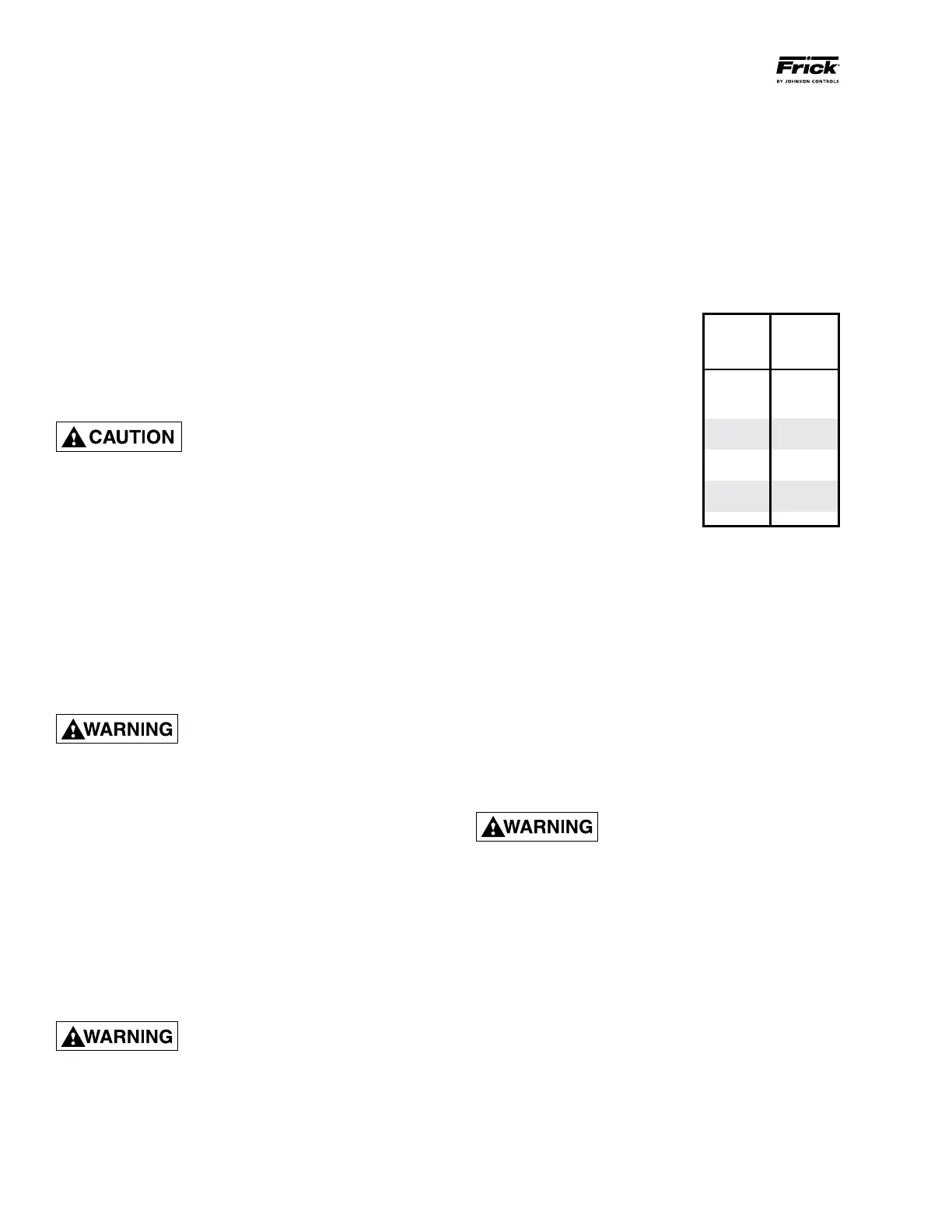
OIL CHARGE
The normal charging level is midway in the top sight glass
located midway along the oil separator shell. Normal oper-
ating level is midway between the top sight glass and
bottom sight glass. The table gives the approximate oil
charge quantity.
* Includes total in oil separator and piping. Additional oil sup‑
plied for oil cooler.
Add oil by attaching the end of a
suitable‑pressure‑type hose to the
oil charging valve, located on the
top of the oil separator at the com‑
pressor end. Using a pressure‑type
pump and the recommended Frick
oil, open the charging valve and
pump oil into the separator. NOTE:
Fill slowly because oil will fill up
in the separator faster than it
shows in the sight glass.
Oil distillers and similar equipment
which act to trap oil must be filled
prior to unit operation to normal design outlet levels. The
same pump used to charge the unit may be used for filling
these auxiliary oil reservoirs.
NOTE: The sight glass located in the coalescing end
of the separator near the discharge connection should
remain empty.
OIL HEATER(S)
Standard units are equipped with two or three 500 watt oil
heaters, providing sufficient heat to maintain the oil tempera‑
ture for most indoor applications during shutdown cycles
to permit safe start‑up. Should additional heating capacity
be required because of low ambient temperature, contact
Frick. The heaters are energized only when the unit is not
in operation.
DO NOT ENERGIZE THE HEATERS
when there is no oil in the unit, the
heat ers will burn out. The oil heat-
ers will be energized whenever 120 volt control power
is applied to the unit and the com pressor is not run ning,
unless the 16 amp circuit breaker in the micro enclosure
is turned off.
60 35
76 35
100 65
134 65
177 110
222 110
270 140
316 140
399 140
480 170
BASIC*
CHARGE
(gal.)
RWB II
MODEL
NO.