RWB II ROTARY SCREW COMPRESSOR UNITS
INSTALLATION
070.200-IOM (DEC 11)
Page 9
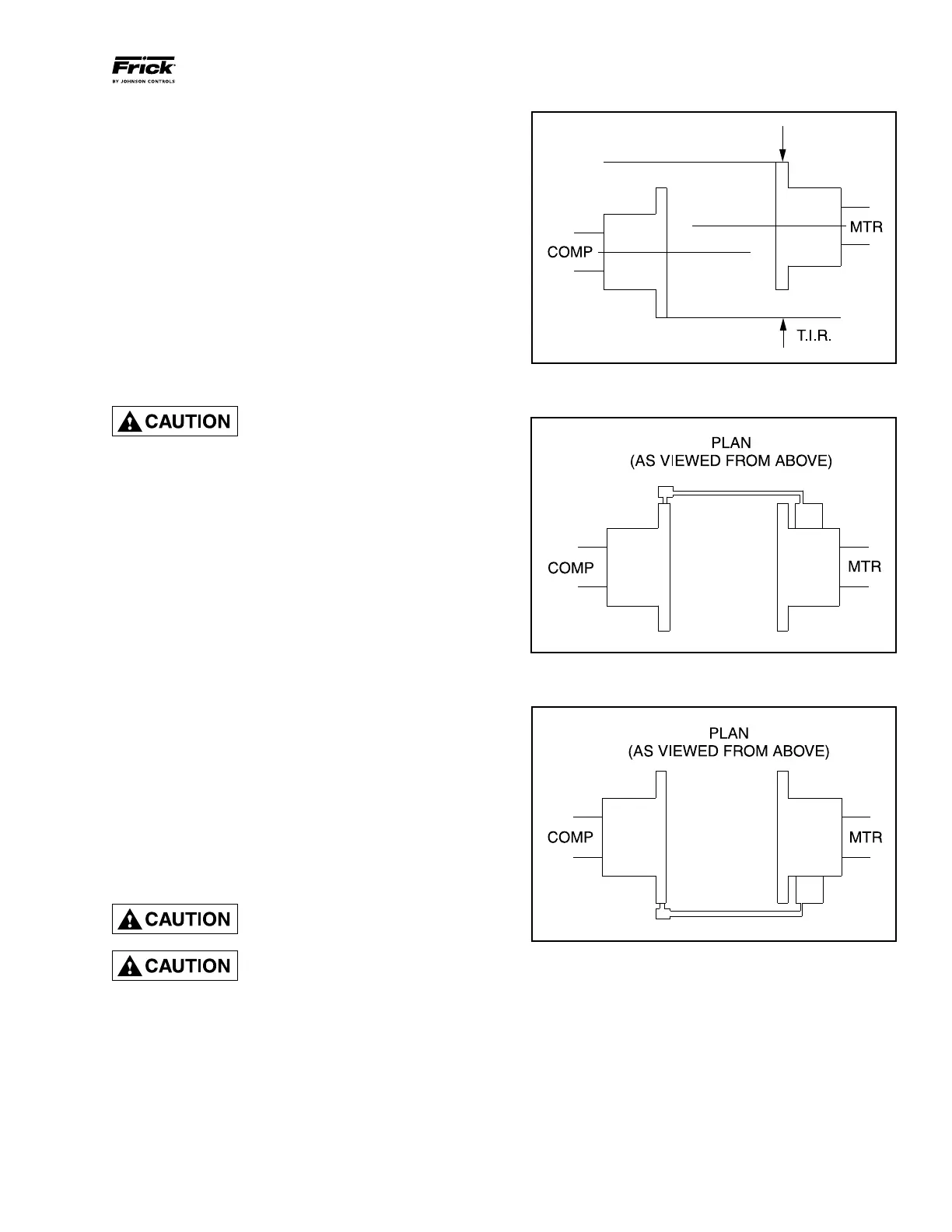
PARALLEL ALIGNMENT
6. To check parallel alignment, as shown in Figure 4, repo‑
sition dial indicator so the stem is in contact with the rim of
the compressor hub, as shown in Figure 5.
Check the dial indicator to be sure that the indicator stem is
slightly loaded so as to allow movement in both directions.
7. Check parallel height misalignment by setting dial indicator
at zero when viewed at the 12 o'clock position. Rotate both
coupling hubs together 180° (6 o'clock position). At this posi‑
tion the dial indicator will show TWICE the amount of parallel
height misalignment.
8. Loosen motor anchor bolts and add or remove shims under
the four motor feet until parallel height misalignment is within
specified tolerance when anchor bolts are retightened.
CARE MUST BE USED WHEN COR-
RECTING FOR PARALLEL MIS-
ALIGNMENT TO ENSURE THAT THE
AXIAL SPACING AND ANGULAR MISALIGNMENT IS NOT
SIGNIFICANTLY DISTURBED.
9. After the parallel height misalignment is within tolerance,
repeat Steps 1 through 5 until angular misalignment is within
specified tolerance.
10. Check parallel lateral misalignment by positioning dial
indicator so the stem is in contact with the rim of the com‑
pressor hub at 3 o'clock, as shown in Figure 6.
Set indicator at zero and rotate both coupling hubs together
180° (9 o'clock position), as shown in Figure 5.
Adjust parallel lateral misalignment using the motor adjusting
screws until reading is within specified tolerance.
11. Recheck angular misalignment and realign if nec‑
essary.
12. Tighten motor anchor bolts and rotate both coupling hubs
together, checking the angular and parallel misalignment
through the full 360° travel at 90° increments. If dial readings
are in excess of specified tolerance realign as required.
13. When the coupling hubs have been aligned to within
specified tolerance, a recording of the cold alignment must
be made for unit records and usage during hot alignment.
Install the coupling guard before
operating the compressor.
When installing drive spacer, make
sure that hub spacing is within
limits shown on the Coupling Data
Table applicable to the coupling being installed and that
the clamping bolt(s) are properly torqued.
Figure 4 - Parallel Misalignment
Figure 5 - Dial Indicator Attached (at 9 o'clock)
Figure 6 - Dial Indicator at 3 o'clock