RWB II ROTARY SCREW COMPRESSOR UNITS
MAINTENANCE
070.200-IOM (DEC 11)
Page 35
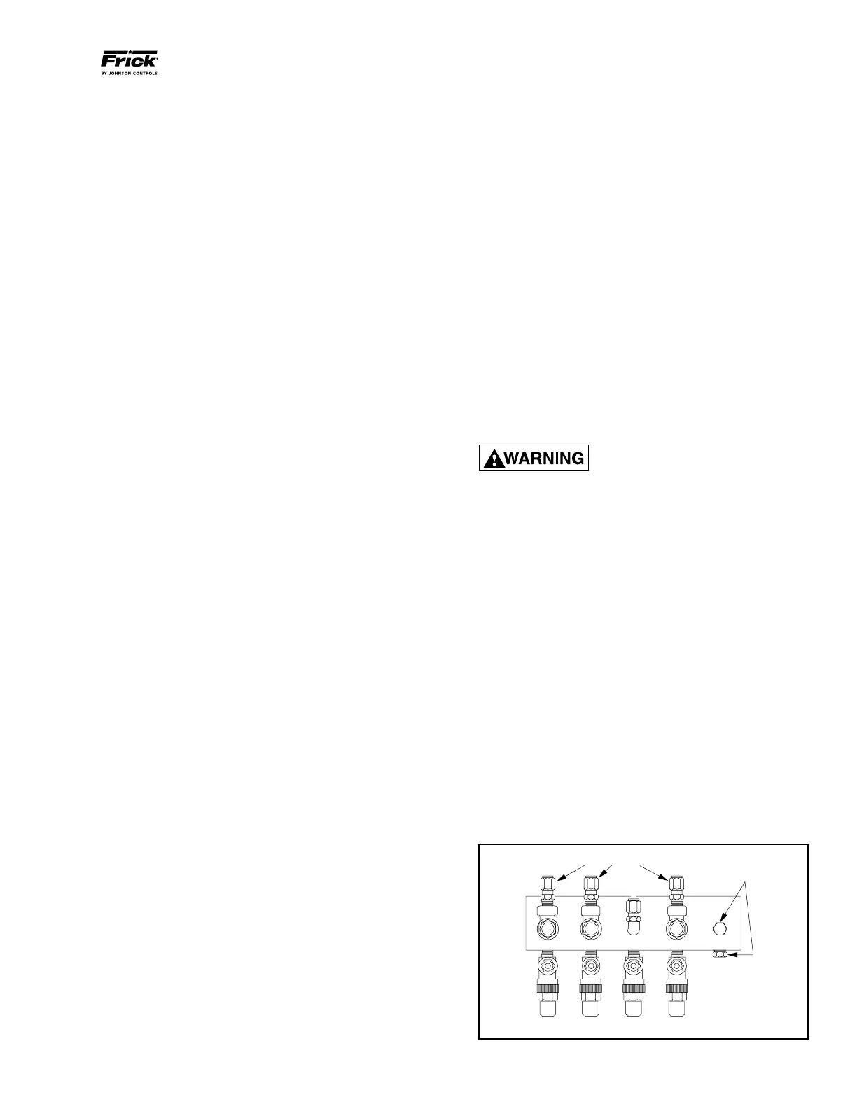
PE-1
PE-5PE-2 PE-3 PE-4
ISOLATION VALVES
PIPE PLUGS
GAUGE/PURGE VALVES
TROUBLESHOOTING GUIDE
Successful problem solving requires an organized ap proach
to define the problem, identify the cause, and make the proper
correction. Sometimes it is possible that two relatively obvi‑
ous problems combine to provide a set of symptoms that can
mislead the troubleshooter. Be aware of this possibility and
avoid solving the “wrong problem”.
ABNORMAL OPERATION
ANALYSIS and CORRECTION
Four logical steps are required to analyze an opera tional
problem effectively and make the necessary correc tions:
1. Define the problem and its limits.
2. Identify all possible causes.
3. Test each cause until the source of the problem is found.
4. Make the necessary corrections.
The first step in effective problem solving is to define the
limits of the problem. If, for example, the compressor peri‑
odically experiences high oil tempera tures, do not rely on
this observation alone to help identify the problem. On the
basis of this information the apparent corrective measure
would appear to be a readjustment of the liquid injection
system. Lowering the equalizing pres sure on the thermal
expansion valve would increase the refriger ant feed and the
oil temperature should drop.
If the high oil temperature was the result of high suction
superheat, however, and not just a matter of improper liquid
injection adjustment, increasing the liquid feed could lead to
other problems. Under low load conditions the liquid injection
system may have a tendency to overfeed. The high suction
superheat condition, moreover, may only be temporary. When
system conditions return to normal the units’ liquid injection
will overfeed and oil temperature will drop. In solving the
wrong problem a new problem was created.
When an operating problem develops compare all operat ing
information on the MAIN OPERATING SCREEN with normal
operating conditions. If an Operating Log has been maintained
the log can help determine what constitutes normal operation
for the compressor unit in that particular system.
The following list of abnormal system conditions can cause
abnormal operation of the RWB II compressor unit:
1. Insufficient or excessive refrigeration load.
2. Excessively high suction pressure.
3. Excessively high suction superheat.
4. Excessively high discharge pressure.
5. Inadequate refrigerant charge or low receiver level.
6. Excessively high or low temperature coolant to the oil
cooler.
7. Liquid return from system (slugging).
8. Refrigerant underfeed or overfeed to evaporators.
9. Blocked tubes in water cooled oil cooler from high mineral
content of water.
10. Insufficient evaporator or condenser sizing.
11. Incorrect refrigerant line sizing.
12. Improper system piping.
13. Problems in electrical service to compressor unit.
14. Air and moisture present in the system.
Make a list of all deviations from normal plant operation and
normal compressor unit operation. Delete any items which
do not relate to the symptom and separately list those items
that might relate to the symptom. Use the list as a guide to
further investi gate the problem.
The second step in problem solving is to decide which items
on the list are possible causes and which items are additional
symptoms. High discharge temperature and high oil tem‑
perature readings on a display may both be symptoms of a
problem and not casually relat ed. High suction superheat or
a low receiver level, however, could cause both symptoms.
The third step is to identify the most likely cause and take
action to correct the problem. If the symptoms are not relieved
move to the next item on the list and repeat the procedure
until you have identified the cause of the problem. Once the
cause has been identi fied and con firmed make the necessary
correc tions.
SERVICING THE COLD-START VALVE
DO NOT ATTEMPT TO SERVICE THE
COLD START VALVE. PLEASE CON-
TACT THE FRICK SERVICE DE-
PARTMENT.
PRESSURE TRANSDUCERS - TESTING
Pressure transducers, Figure 30, are located on a covered
manifold near the microprocessor console.
1.
Shut down the compressor and allow pressures to
equalize.
2. Isolate suction transducer PE‑4 from the unit and depres‑
surize. NOTE: Recover or transfer all refrigerant vapor,
in accordance with local ordinances, before opening to
atmosphere.
3. Measure the voltage of PE‑4 on connector P4 (terminals
WHT and BLK) on the SBC with a digital voltmeter.
4. The voltage reading should be 1.48 VDC to 1.72 VDC at
standard atmospheric pressure (14.7 PSIA or 0 PSIG). When
checking transducers at higher elevations, an allowance in
the readings must be made by subtracting approximately 0.02
VDC per 1000 feet of elevation above sea level. Therefore,
if PE‑4 is measured at 5000 feet elevation under relatively
normal weather conditions, the output voltage should differ
by 0.10 VDC to read between 1.38 VDC and 1.62 VDC.
Figure 30