RWB II ROTARY SCREW COMPRESSOR UNITS
INSTALLATION
070.200-IOM (DEC 11)
Page 7
All rotating power transmission equipment is potentially dangerous. Ensure that the couplings are
properly guarded prior to turning on the power. Coupling guards are provided with the equipment
and must be in place and secured properly while the equipment is in operation.
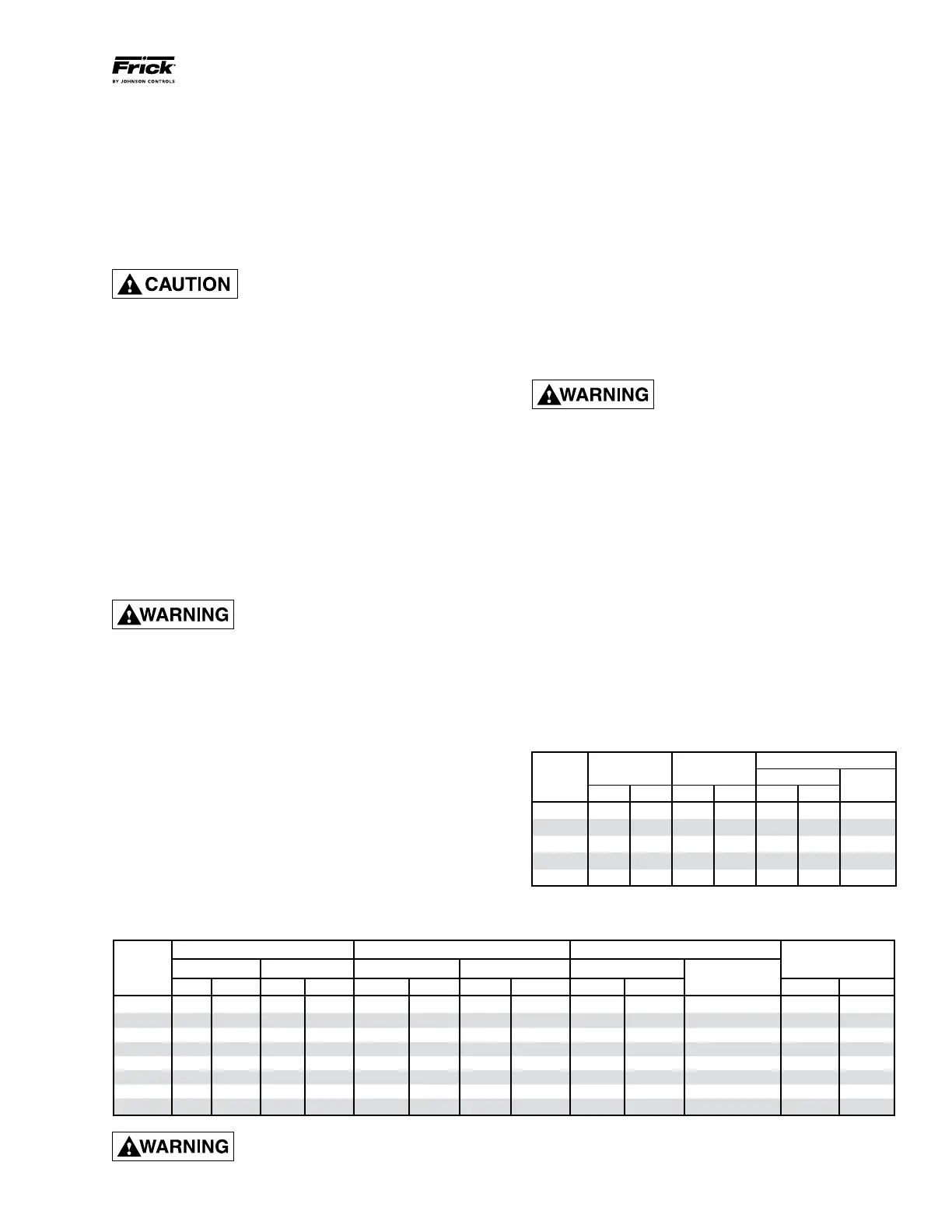
SERIES 52 COUPLING DATA TABLE
3. Adjust the distance between hub faces as specified in the
DBZ‑B Data Table by sliding the hubs. Key and secure hubs
to the shafts by tightening setscrews.
4. Reinstall the eight previously removed bolts and locknuts.
Alternately tighten each locknut as you would the lug nuts on
an automobile. NOTE: ALWAYS TURN THE NUT. NEVER
TURN THE BOLT.
5. Torque the locknuts to the value shown in the DBZ‑B Data
Table for the size coupling being installed.
Lubricated and/or plated bolts and
locknuts develop higher bolt ten-
sion with less tightening than those
that are dry and not plated. Torques for lubricated and/or
plated bolts and locknuts will generally fall in the lower range;
while those that are dry or as received from the factory fall
into the upper range. Torque readings should be ob served
while locknut is being turned.
6. Proceed to coupling alignment.
SERIES 52 COUPLING – The Thomas Series 52 coupling is
also used on applications above 600 HP. It has two drive hubs,
a center spool, and disc packs which are bolted between the
center spool and each drive hub. A center spool and two flex‑
ible steel disc packs serve as the drive element. These three
parts, situated between the motor and compressor hubs,
prevent axial end float between the motor and compressor
shafts. End float tends to occur with sleeve bearing motors.
The magnetic center of the sleeve bearing motors must be
determined and maintained by securing the coupling hub to
the motor shaft with the shaft properly located.
Injury may occur if loose clothing,
etc. becomes entangled on the
spinning motor shaft.
If the motor is coupled to the compressor using a fixed‑end‑
play coupling such as the Series 52 coupling and the motor
is not properly centered, the additional thrust loads will be
transmitted to the compressor bearings. This additional thrust
could result in premature bearing failure. Install as follows:
1. Before proceeding with the alignment process found
on pages 7 and 8 of this manual, disassemble the Series
52 coupling noting the arrangement of bolts, washers,
and nuts as THEY MUST BE REPLACED IN THE SAME
ORDER. Mark the adjoining bolt holes of each part, the two
hubs, the two disc packs, and the center spool, so they are
put back together in the same position.
2. Mount the coupling hubs on their respective shafts. The
hub is bored for an interference fit on the shaft. Heating of
the coupling hub may be necessary for assembly. DO NOT
SPOT HEAT THE HUB as it may cause distortion. Heat in
water, oil, or use a SOFT open flame and quickly position
on the shaft.
3. Adjust the distance between hub faces, as specified in the
Series 52 Coupling Data Table, by sliding the hubs. Key and
secure the hubs to the shafts by tightening the set screws.
4. Reassemble the coupling with the disc packs and the
center spool. Ensure that they are reassembled exactly as
they were disassembled.
WOODS BP SERIES COUPLING – is also used on appli‑
cations above 600 HP. It utilizes a center spool and two flex‑
ible steel disc packs as the drive element. These three parts,
situated between the motor and compressor hubs, prevent
axial end float between the motor and compressor shafts.
End float tends to occur with sleeve bearing motors.
Injury may occur if loose clothing,
etc. becomes entangled on the
spinning motor shaft.
If the motor is coupled to the compressor using a fixed‑end‑
play coupling and the motor is not properly centered, the
additional thrust loads will be transmitted to the compressor
bearings. This additional thrust could result in premature
bearing failure. Install the BP Series coupling using the fol‑
lowing instructions:
1. Before proceeding with the alignment process in the fol‑
lowing section, disassemble the BP Series coupling noting
the arrangement of bolts, washers, and nuts as THEY
MUST BE REPLACED IN THE SAME ORDER. Mark the
adjoining bolt holes of each part, the two hubs, the two disc
packs, and the center spool, so they are put back together
in the same position.
2. Install the motor and compressor coupling hubs on their
respective shafts with the keys. Ensure that the hubs slide,
so that when the shim packs are installed, no axial stresses
are transferred to the shim packs because the coupling hub
is stuck.
COUP-
HUB FACE MAX TOTAL INDICATOR READING SETSCREW
CLAMP BOLT
LING
SPACING +/- ANGULAR PARALLEL TORQUE (LUBE) TORQUE (LUBE)
SIZE in. mm in. mm in. mm in. mm ft-lb Nm
SIZE
ft-lb Nm
225 5 127 1/32 0.914 0.004 0.102 0.004 0.102 7.5 10.5 1/4‑20 UNRF 25 33.9
262 5 127 1/32 0.914 0.004 0.102 0.004 0.102 22 30.6 3/8‑24 UNRF 30 40.7
312 5½ 139.7 3/64 1.295 0.004 0.102 0.004 0.102 37 51.5 7/16‑20 UNRF 40 54.2
350 6 152.4 3/64 1.295 0.004 0.102 0.004 0.102 55 76.5 1/2‑20 UNRF 95 128.8
375 7 177.8 1/16 1.574 0.004 0.102 0.004 0.102 55 76.5 1/2‑20 UNRF 130 176.3
425 7 177.8 1/16 1.574 0.004 0.102 0.004 0.102 96 133.6 5/8‑18 UNRF 175 237.3
450 8 203.2 1/16 1.574 0.004 0.102 0.004 0.102 96 133.6 5/8‑18 UNRF 200 271.2
500 9 228.6 5/64 2.083 0.004 0.102 0.004 0.102 250 348 7/8‑14 UNRF 260 352.5
BP SERIES COUPLING DATA TABLE
BP HUB FACE * DISC PACK CLAMP BOLT
SERIES SPACING BOLT TORQ. TORQ. DRY SIZE
SIZE in. mm ft-lb Nm ft-lb Nm UNF
BP48 4.88 124 40 54 41 56
3
/
8
‑24
BP53 5.88 150 60 81 65 88
7
/
16
‑20
BP58 6.00 152 120 163 100 136
1
/
2
‑20
BP58 6.69 170 120 163 100 136
1
/
2
‑20
BP63 7.00 179 120 163 100 136
1
/
2
‑20
* Max total indicator reading .003 in. or .076 mm for all sizes.