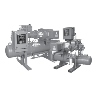
RWB II PLUS ROTARY SCREW COMPRESSOR UNITS
FORMS
070.200-IOM (DEC 11)
Page 54
RWB II COMPRESSOR PRESTART CHECKLIST
The following items MUST be checked and completed by the installer prior to the arrival of the Frick Field Service Supervisor.
Details on the checklist can be found in this manual. Certain items on this checklist will be reveried by the Frick Field
Service Supervisor prior to the actual start-up.
Mechanical Checks
__ Conrmthatmotordisconnectisopen
__ Isolatesuctionpressuretransducer
__ Pressuretestandleakcheckunit
__ Evacuateunit
__ Removecompressordrivecouplingguard
__ RemovecouplingcenterandDO NOT reinstall
(motorrotationmustbecheckedwithoutcenter)
__ Checkforcorrectpositionofallhand,stop,andcheck
valvesPRIORtochargingunitwithOILorREFRIGERANT
__ Chargeunitwithcorrecttypeandquantityofoil
__ LubricateelectricdrivemotorbearingsPRIORto
checkingmotorrotation
__ Checkoilpumpalignment(ifapplicable)
__ Checkforcorrecteconomizerpiping(ifapplicable)
__ Checkseparatesourceofliquidrefrigerantsupply(if
applicable,liquidinjectionoilcooling)
__ Checkwatersupplyforwater-cooledoilcooler(ifap-
plicable,watercooledoilcooling)
__ Checkthermosyphonreceiverrefrigerantlevel(ifap-
plicable,thermosyphonoilcooling)
__
CheckforPROPER PIPE SUPPORTSandcorrectfoundation
__ ChecktoensureALLpipingINCLUDING RELIEF VALVES
iscompleted
Electrical Checks
__ Conrmthatmaindisconnecttomotorstarterandmicro
isopen
__ Conrmthatelectricalcontractorhasseenthissheet,
ALL PERTINENT WIRINGinformation,anddrawings
__ Conrmproperpowersupplytothestarterpackage
__ Conrmpropermotorprotection(breakersizing)
__ Conrmthatallwiringusedisstrandedcopperandis
14AWGorlarger(sizedproperly)
__ Conrmall120voltcontrolwiringisruninaseparate
conduitfromallhighvoltagewiring
__ Conrmall120voltcontrolwiringisruninaseparate
conduitfromoilpumpandcompressormotorwiring
__ Conrmnohighvoltagewiringentersthemicropanel
atanypoint
__ Checkcurrenttransformerforcorrectsizingandinstal-
lation
__ Checkallpoint-to-pointwiringbetweenthemicroand
motorstarter
__ Conrm all interconnections between micro, motor
starter,andthesystemaremadeandarecorrect
__ Ensureall electrical panels are free from installation
debris,METALPARTICLES,andmoisture
After the above items have been checked and veried:
__ Closethemaindisconnectfromthemainpowersupplytothemotorstarter
__ Closethemotorstarterdisconnecttoenergizethemicro
__ Manuallyenergizeoilpumpandcheckoilpumpmotorrotation
__ Manuallyenergizecompressordrivemotorandcheckmotorrotation
__ Leavemicroenergizedtoensureoilheatersareonandoiltemperatureiscorrectforstart-up
Summary: The Frick Field Service Supervisor should arrive to nd the above items completed. He should
nd an uncoupled compressor drive unit (to verify motor rotation and alignment) and energized oil heaters
with the oil at the proper standby temperatures. Full compliance with the above items will contribute to a
quick, efcient and smooth start-up.
The Start-up Supervisor will:
1.Verifypositionofallvalves
2.Verifyallwiringconnections
3.Verifycompressormotorrotation
4.Verifyoilpumpmotorrotation
5.Verifythe%ofFLAonthemicrodisplay
6.Verifyandnalizealignment(ifapplicable)
7.Calibrateslidevalveandslidestop
8.Calibratetemperatureandpressurereadings
9.Correctanyprobleminthepackage
10.Instructoperationpersonnel
NOTE: Customer connections are to be made per the electrical diagram for the motor starter listed under
the installation section and per the wiring diagram in the Quantum maintenance manual.
Please complete and sign this form & fax to 717-762-8624 as conrmation of completion.
FrickSalesOrderNumber:______________________
CompressorModelNumber:_____________________
UnitSerialNumber:____________________________
EndUserName: _______________________________
AddressofFacility:_____________________________
City,State,Zip:________________________________
PrintName:___________________________________
Company:_____________________________________
JobSiteContact:_______________________________
ContactPhoneNumber:_________________________
Signed: ______________________________________

 Loading...


