Engineering manual - SAB 193-233-283 S A-frame (including ATEX)
104/168
008831 en 2020.10
Installation instructions
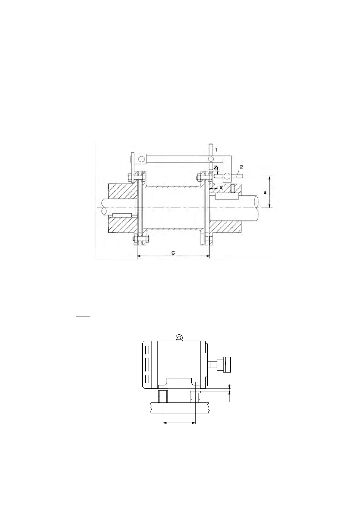
Achieving parallel shafts in horizontal plane
• Turn the coupling so that the alignment gauge is in upper position.
• Guide the measuring pin (pos. 2) towards the coupling flange, using a 1.0 mm feeler
gauge, and fix the pin. Remove the feeler gauge
• Rotate the coupling 180° and measure the change in distance from the measuring pin to
the flange, using feeler gauges. This change is called "x".
• Measure the distance “b” between the motor feet as shown in Fig. 75. Measure the dis-
tance “a” from the centre of the pin, pos. 2, to the centre of the motor as illustrated in
Fig. 74.
Fig. 74
Insert shims of thickness "y" either under both front feet or both rear feet, thereby tilting the mo-
tor in the direction required. Shim thickness "y" is calculated by using the following formula (see
also Fig. 75):
Fig. 75
After tightening the motor bolts, repeat the measurement and compare the result to the values in
Table 26.
Motor shaft
Compressor
shaft