Engineering manual - SAB 355 Screw compressor unit (including ATEX)
004100 en 2020.10
45/156
Technical description
However, the discharge gas still contains a certain amount of fine oil drops which is separated as
the discharge gas passes the fine oil separator elements (the fine filters). This oil is returned
to the compressor in separate piping systems as described later in this section.
As the velocity and specific weight of the gas influences the efficiency of the fine oil separator ele-
ments, the units are available in two executions according to the following guidelines:
• Refrigerants HFC and HCFC
All unit types SM-LM-SF and LF are delivered with two built-in fine filters and both con-
necting branches, 27A and 27B, are connected to the refrigeration plant.
• Refrigerant R717
All unit types LM-SF og LF are delivered with two built-in fine filters and both connecting
branches, 27A and 27B, are connected to the refrigeration plant.
Unit type SM is delivered with one fine filter and only the open connecting branch, 27A/
27B, is connected to the refrigeration plant.
Normally, the fine oil separator elements do not need to be inspected but if it is considered neces-
sary - e.g. if observing increased oil consumption in the unit - they can be removed through the
ends of the oil separator.
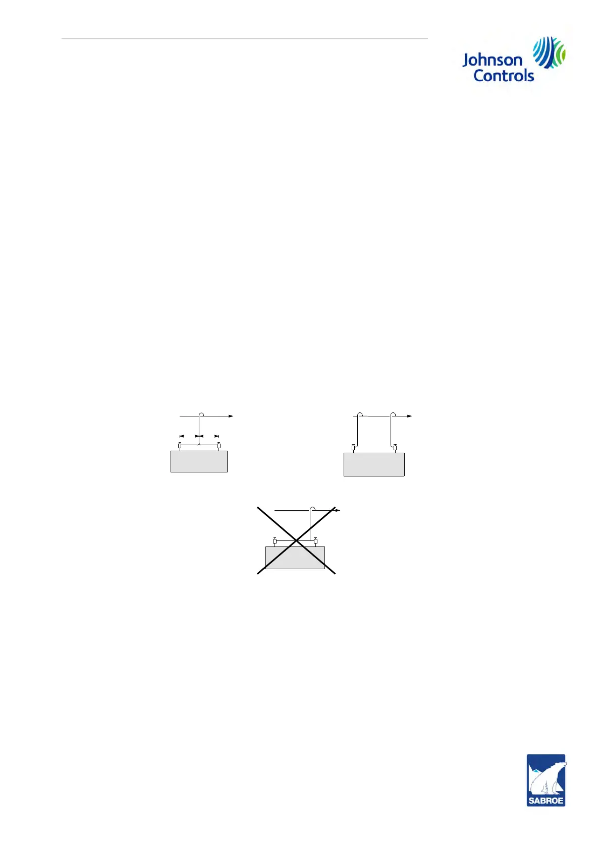
For units with two fine filters it is essential that the pressure loss through the oil separator and the
piping system is the same in both passes. This requires that the pipe connections from the oil sep-
arator to the refrigeration plant are of equal length and as symmetrical as possible, see Fig. 1 and
2 in Fig. 22. The asymmetrical principle sketch in fig. 3 should be avoided.
Fig. 22: Pipe connections from oil separator
Oil return system for fine filter element
Whether the unit is delivered with one or two discharge stop valves, thus with one or two fine
oil separator elements, two oil return pipes will be fitted on the unit. See piping diagram.
Throttle valves pos. 52 are used for adjustment of the oil flow through the oil return systems.
Their adjustment is just enough to make the pipelines feel warm during operation. In general, it is
recommended not to open the throttle valves more than 4 turns. At the same time gas bubbles
should be visible in sight glass pos. 53.
Oil vessel
As already mentioned, the lubricating oil is collected in the oil vessel. The oil level in the vessel
must always be visible in the sight glasses pos. 31. The correct amount of oil in the unit is stated
in Table 34: Oil charge in section 11.15 Oil charge.
xx
To condenserTo condenser
Fig. 1Fig. 2
Fig. 3