ACU-5000 Operations Manual
Interoperability Now 3-1
3 Interface Capabilities
3.1 Scope
This section provides a basic explanation of the various interfaces available with the ACU-5000’s
twelve external communications channels: Radio (4-wire), VoIP, RoIP, and PSTN (2-wire). The
system also has a handset interface to assist setup and provide a local communications capability.
3.2 Radio Interface
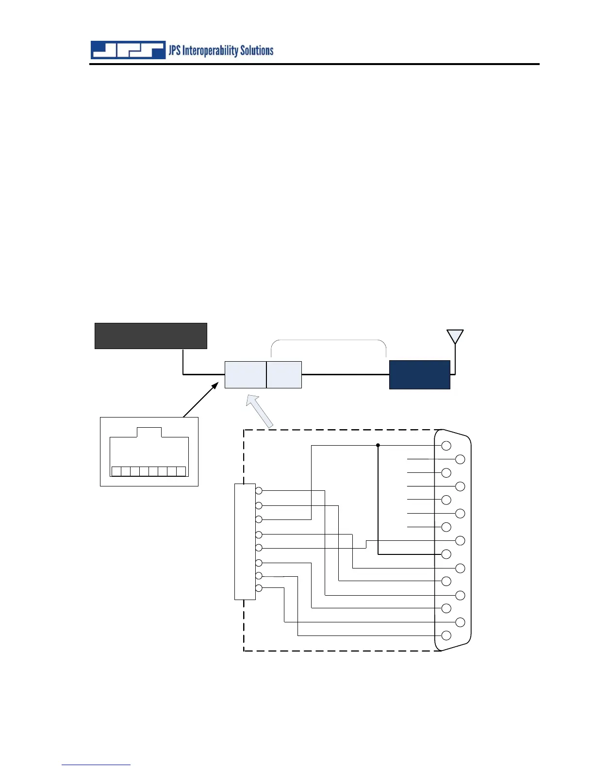
The physical interfaces for the radio ports (and other four-wire devices) are twelve RJ-45
connectors. Radios are connected to the ACU-5000 via a cable that is likely to include interfacing
circuitry (such as is used with JPS radio cables). Adapter cables (RJ-45 to D15) allow the use of
the very large library of JPS radio cables already in existence, including standard Military 5 and
6 pin microphone connectors. These cables allow connection to hundreds of commonly-deployed
radios. See Table 1-4. Other cables can be designed and built on request. The JPS Customer
Service Department can be reached by phone at (919) 790-1011, or by FAX at (919) 790-1456.
A representative will explain what is required.
Figure 3-1 RJ-45 Radio Ports