15
3-1
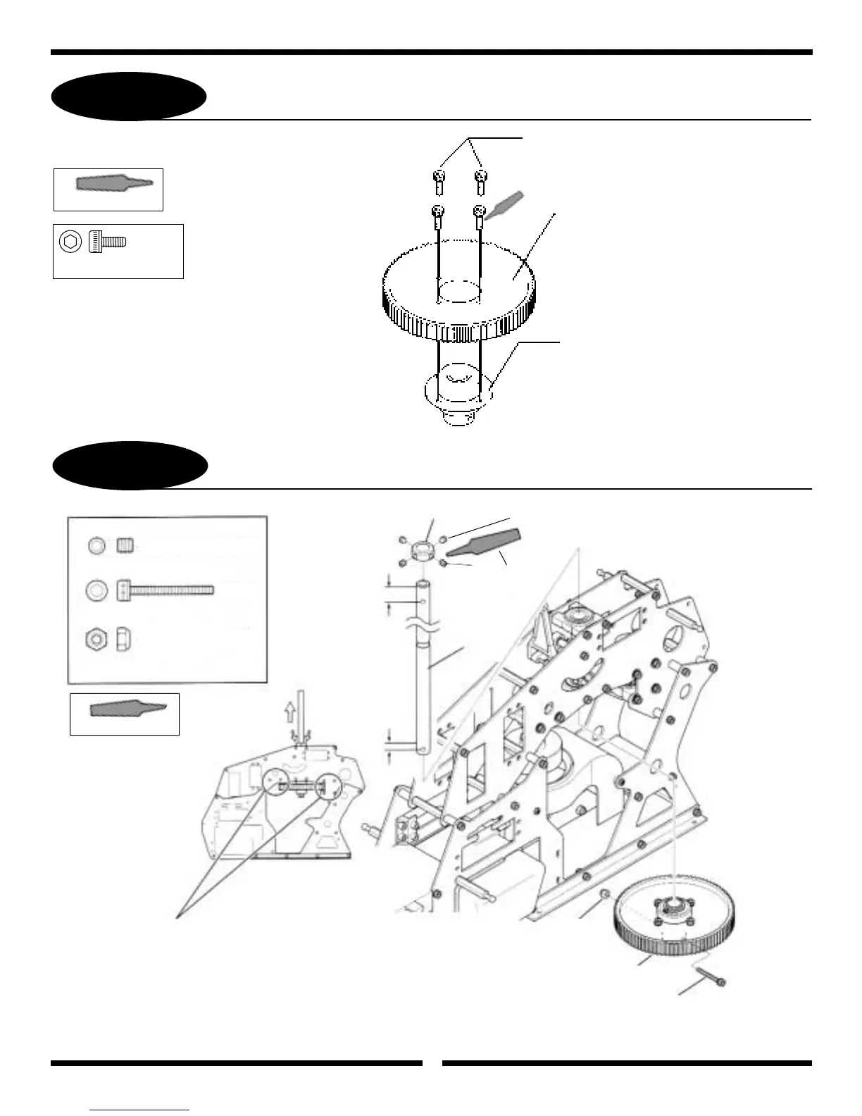
MAIN DRIVE GEAR/AUTOROTATION ASSEMBLY
3-2
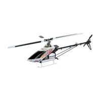
MAIN DRIVE GEAR/AUTOROTATION ASSEMBLY INSTALLATION
3x6mm Socket Head Bolt
2. Secure the Autorotation Hub to the Main Rotor
Shaft using the 3x22mm Socket Head Bolt. Next,
slide the Main Shaft Collar onto the Main Rotor
Shaft. While pulling upward on the Main Rotor
Shaft, secure the Main Shaft Collar to the Main
Rotor Shaft using the four 4x4mm Set Screws.
1. Once the Main Shaft Assembly is in place,
adjust the gear mesh of the Clutch Bell
and Tail Belt Pinion Gears and secure the bolts
left loose from Step 2-1.
3x6mm Socket Head Bolt (4 pcs)
[Tighten equally to prevent
warping of Main Drive Gear]
Main Drive Gear
Use Threadlock
Autorotation Assembly
Main Shaft Collar
4x4mm Set Screw
3x22mm Socket Head Bolt
3mm Lock Nut
8mm
3mm
Main Rotor
Shaft
Use Threadlock
3mm Lock Nut
Autorotation
Assembly from
Step 3-1
3x22mm Socket
Head Bolt
Use Blue Threadlock
. . . . . . . . . . . . . 4 pcs
. . 1 pc
. . . . . . . . . . . . . . 1 pc
......4 pcs
Use Blue Threadlock
4x4mm Set Screws (4)