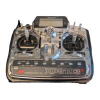
The XP8
10
3 of
fers three (3) separate throttle cur
ves with five (5)
adjustable points per cur
ve. This function allows you to
customize the throttle cur
ve and pitch cur
ve together to maximize
engine per
for
mance at a par
ticular pitch setting. Once the
throttle cur
ves are established, each can be activated in flight
using the three (3) position flight mode switch. The flight switch
of
fers three (3) selectable cur
ves. N=Nor
mal, 1=Stunt 1,
2=Stunt 2
The N, or Nor
mal, position should be used for hovering.
Positions 1 and 2, or Stunt 1 and Stunt 2, should be used for
aerobatic maneuvers and for
ward flight.
Note:
The throttle trim and hovering throttle knobs are only
operable when the flight mode switch is in the Nor
mal position.
Thus, in the 1 or 2 positions, these two functions have no ef
fect.
Each of the five (5) positions of the throttle cur
ve are
independently adjustable from 0
-
1
00%. These five (5) positions
correspond to the position of the throttle stick.
The transmitter is factor
y preset to the throttle cur
ve as indicated
by the solid line in the figure below. Individual middle points can
be activated and increased/decreased to suit your specific
needs.
Point output value
Switch the Flight Mode
position by pressing SEL
(Display will flash whe

 Loading...