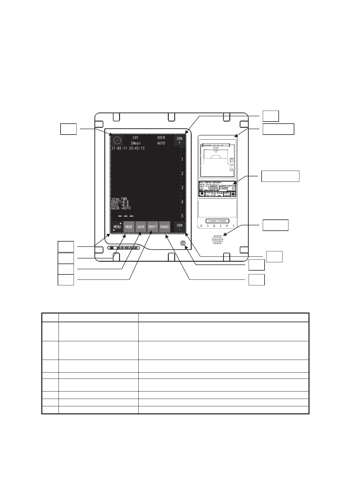
2. Control Panel
2-1
2. Control Panel
This section describes the names and functions of the control panel and its controls.
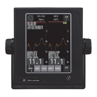
The screen shown below is defined as the main screen.
図2-1 表示処理装置と画面
Figure 2-1 Display processing unit and Main screen
No. Key Function
1
○
I
Switches the equipment power on and off.
Turn on and off: Press
○
I button
2
MENU Displays the menu screen.
To return the main screen, press the MAIN key since the MENU key
will change to the MAIN key.
3
○
✓
When occurring alert, the icon will change depend on alert status.
And alert content will be displayed to the right of the icon.
4 DIM+/DIM- Adjusts the screen brilliance.
5
MODE Switches the display modes in order of STD mode, HIST mode,
DOCKING mode repeatedly.
6
GAIN Adjusts the sensitivity high or low.
7
DRAFT Sets the draft.
8
RANGE Switches the depth range to shallow or deep.
Note:
When the power is turned on by a breaker while all the power supply to the equipment is cut
off, the equipment will automatically start up without pressing the power button. In this time, it
may take one minute from the startup screen to the main screen.
Printer
Name Plate
Buzzer
1
2
3
4
4
5
6
7 8