2-2
2
• Avoid having a rope or signal flag from winding around the radiating section thereby
preventing it from rotating.
• Avoid the effects of dust and heat caused by smoke from a chimney.
• When determining the appropriate antenna height and installation location, take into
consideration the reduction of vibration, the strength of the hull and the antenna mount base,
and maintenance properties.
• Provide for maintenance space: platform, safety link, hand rail, steps, etc. The lower edge
of a radar antenna should be a minimum of 500 mm above any safety rail.
• When installing the scanner, select a location where there are the fewest structural objects in
the surrounding area so that the capability to drive the motor will not be depressed by the
non-equability wind which is likely to rotate the scanner.
2) Electrical selection criteria
• The installation height of the antenna relates to the maximum detection distance. The
higher, the better. However, if it is too high, radio wave energy greatly attenuates above the
antenna's vertical beam width (the point -3dB from the peak of the main lobe). As a result,
it is difficult to detect a close-in target. Sea clutter also increases. Determine the
installation height by taking into consideration the weight, maximum length of the cable, and
maintenance after installation.
• If the installation height of the antenna is low, it is difficult to detect a long distance target.
The ship's mast, derrick, and chimney interfere with radiating beam causing the range that
cannot be viewed on the radar display to increase.
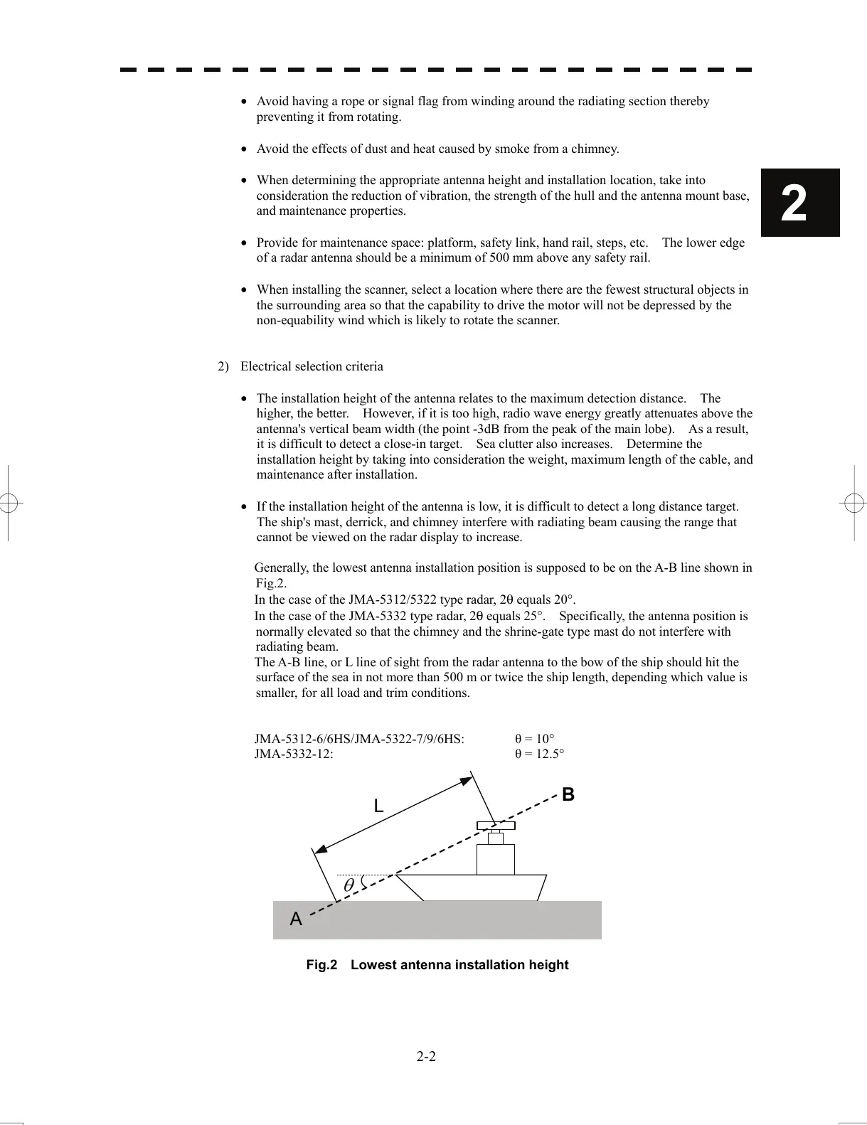
Generally, the lowest antenna installation position is supposed to be on the A-B line shown in
Fig.2.
In the case of the JMA-5312/5322 type radar, 2θ equals 20°.
In the case of the JMA-5332 type radar, 2θ equals 25°. Specifically, the antenna position is
normally elevated so that the chimney and the shrine-gate type mast do not interfere with
radiating beam.
The A-B line, or L line of sight from the radar antenna to the bow of the ship should hit the
surface of the sea in not more than 500 m or twice the ship length, depending which value is
smaller, for all load and trim conditions.
JMA-5312-6/6HS/JMA-5322-7/9/6HS: θ = 10°
JMA-5332-12: θ = 12.5°
L
A
B
Fig.2 Lowest antenna installation height
 Loading...


