3.4 INSTALLATION OF THE POWER CABLE
(CFQ-5436)
This radar equipment comes with 5-m-long cables with a connector.
Wiring table of the cable CFQ-5436
3
Color Number of wires /
diame
ter(mm)
Cross-sectional
area(mm)
Polarity
Red 50/0.18 1.25 +
Red 50/0.18 1.25 +
Red 50/0.18 1.25 +
Black 50/0.18 1.25
-
Black 50/0.18 1.25
-
Black 50/0.18 1.25
-
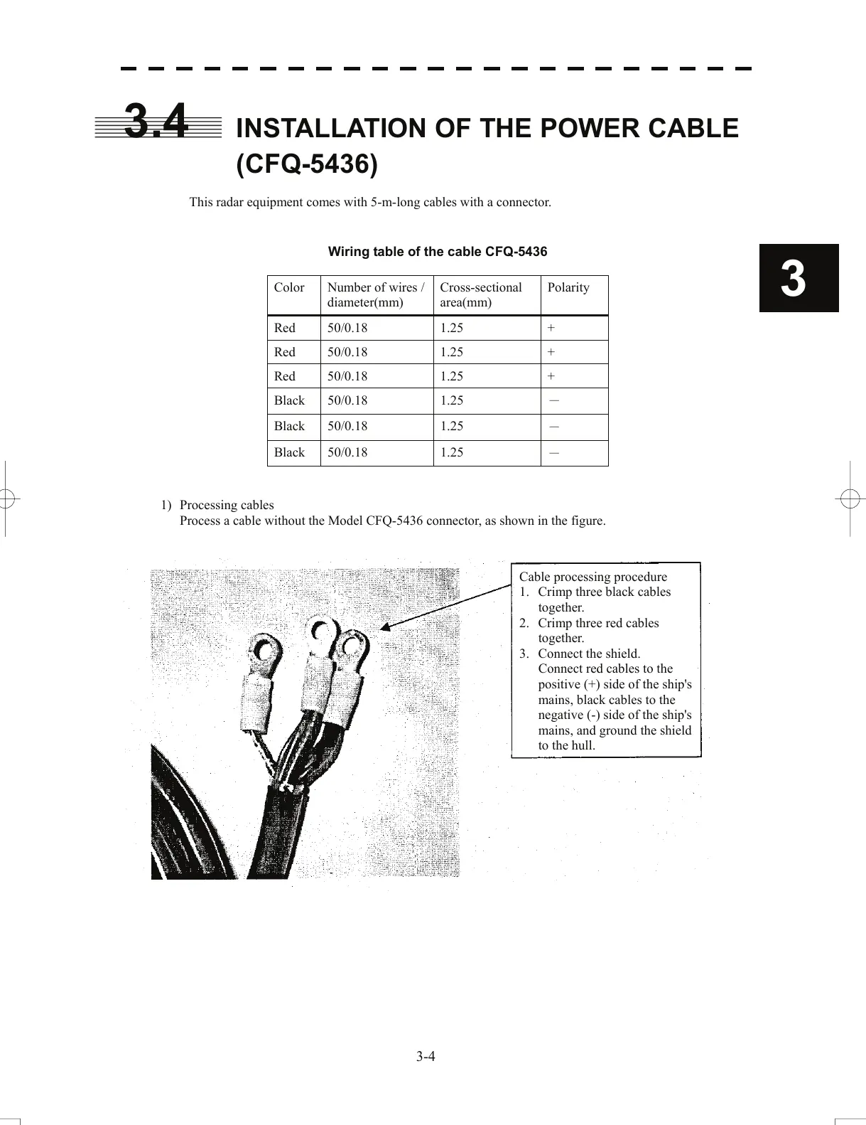
1) Processing cables
Process a cable without the Model CFQ-5436 connector, as shown in the figure.
Cable processing procedure
1. Crimp three black cables
toget
her.
2. Crimp three red cables
toget
her.
3. Connect the shield.
Connect red ca
bles to the
positive (+) side of the ship's
mains, black cables to the
negative (-) side of the ship's
mains, and ground the shield
to the hull.
3-4
 Loading...


