2-1
2.1 SELECTING THE INSTALLATION
POSITION
1) Physical selection criteria
• Install the antenna at the center of the mast on the keel line.
• If the antenna cannot be installed at the above position for some reason, the amount of
deviation must be minimized. And, reinforce the mount base and the platform and take
precautions to protect the antenna from vibration and impact at the installation position.
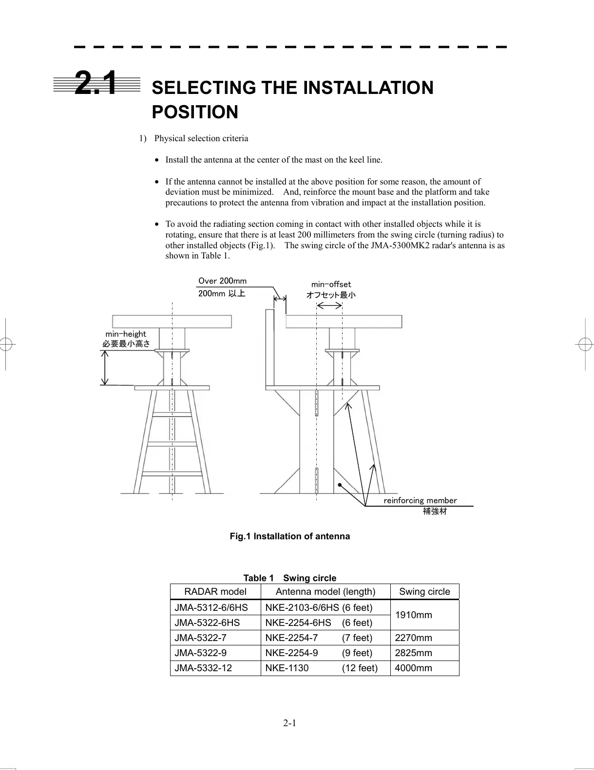
• To avoid the radiating section coming in contact with other installed objects while it is
rotating, ensure that there is at least 200 millimeters from the swing circle (turning radius) to
other installed objects (Fig.1). The swing circle of the JMA-5300MK2 radar's antenna is as
shown in Table 1.
Fig.1 Installation of antenna
Table 1 Swing circle
RADAR model Antenna model (length) Swing circle
JMA-5312-6/6HS NKE-2103-6/6HS (6 feet)
1910mm
JMA-5322-6HS NKE-2254-6HS (6 feet)
JMA-5322-7 NKE-2254-7 (7 feet) 2270mm
JMA-5322-9 NKE-2254-9 (9 feet) 2825mm
JMA-5332-12 NKE-1130 (12 feet) 4000mm
min-height
必要最小高さ
min-offset
オフセット最小
Over 200mm
200mm 以上
reinforcing member
補強材
 Loading...


