3.19 INTERSWITCH UNIT (NQE-3141-4A/8A)
(OPTION)
(1) Connect the radar process unit and interswitch unit with
referen
ce to appendix figure Interconnection
diagram of Radar and Interswitch Unit.
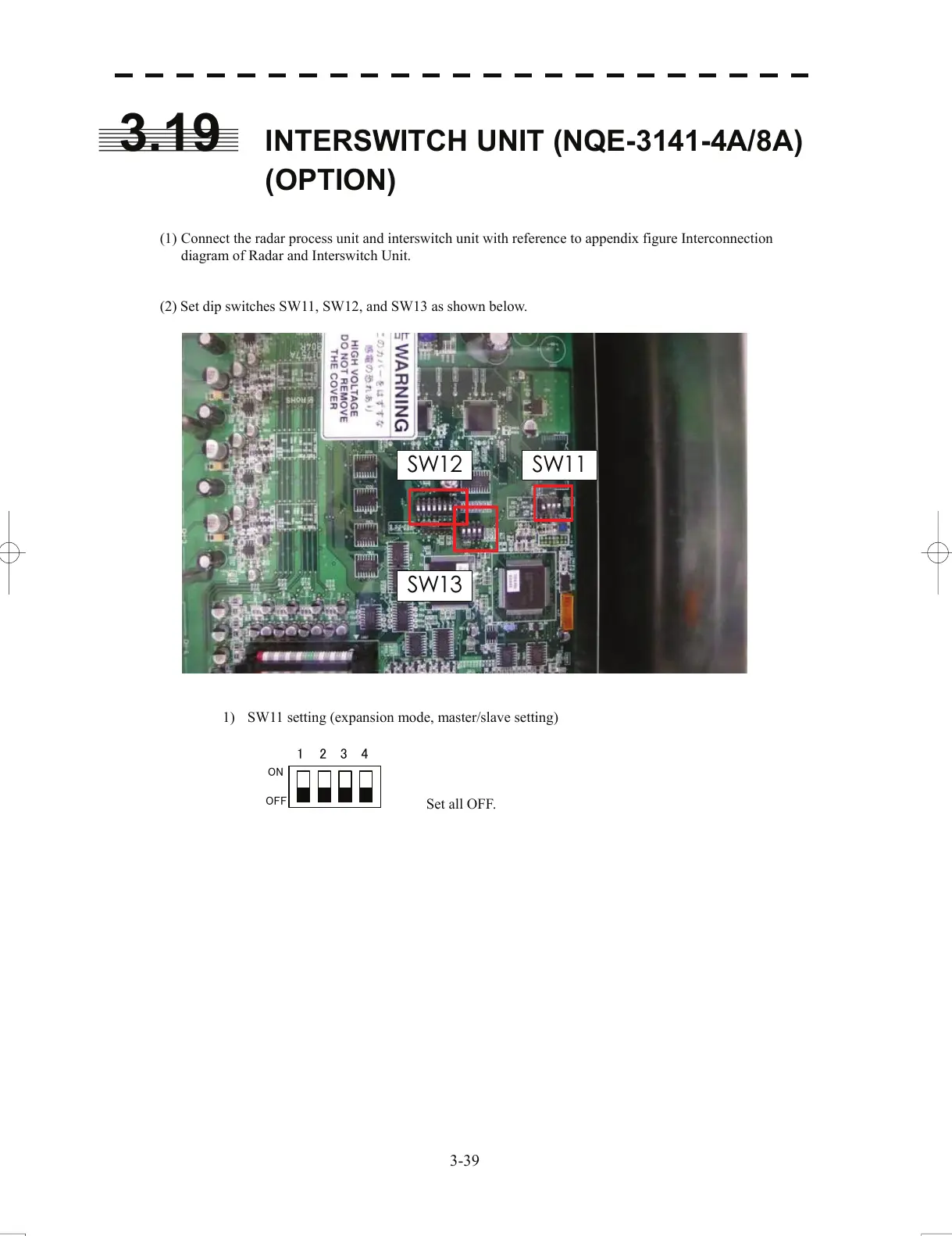
(2) Set dip switches SW11, SW12, and SW13 as shown below.
SW 11
SW 13
SW 12
1) SW11 setting (expansion mode, master/slave setting)
1 234
ON
OFF
Set all OFF.
3-39
 Loading...


