2) SW12 setting (radar connection setting)
Set dip switches based on the number of display unit and scanner unit
Radar Connection Setting
ON No. 1 display unit connected
1
OFF No. 1 display unit NOT connected
ON No. 1 scanner unit connected
2
OFF No. 1 scanner unit NOT connected
ON No. 2 display unit connected
3
OFF No. 2 display unit NOT connected
ON No. 2 scanner unit connected
4
OFF No. 2 scanner unit NOT connected
ON No. 3 display unit connected
5
OFF No. 3 display unit NOT connected
ON No. 3 scanner unit connected
6
OFF No. 3 scanner unit NOT connected
ON No. 4 display unit connected
7
OFF No. 4 display unit NOT connected
ON No. 4 scanner unit connected
8
OFF No. 4 scanner unit NOT connected
3
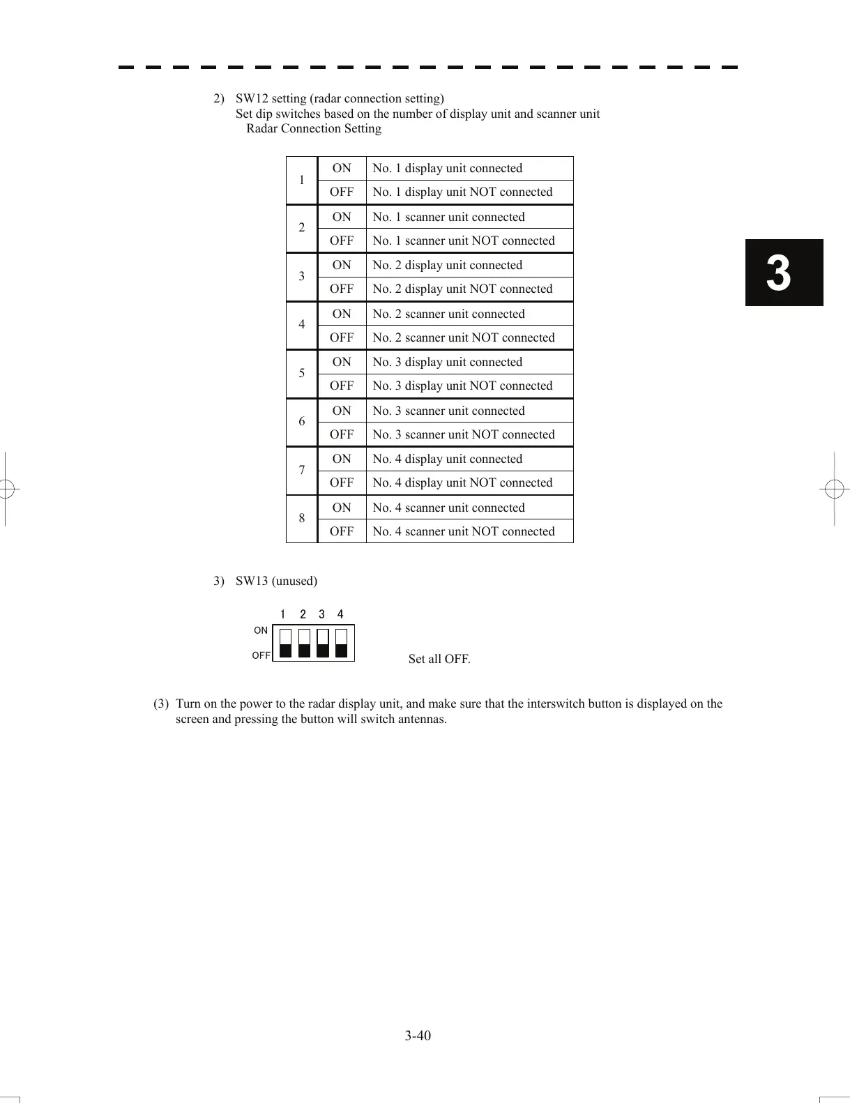
3) SW13 (unused)
1 234
ON
OFF
Set all OFF.
(3) Turn on the power to the radar display unit, and make su
re
that the interswitch button is displayed on the
screen and pressing the button will switch antennas.
3-40
 Loading...


