EasyManuals Logo

JRC JMA-5312-6 Installation Manual

JRC JMA-5312-6
160 pages
To Next Page IconTo Next Page
To Previous Page IconTo Previous Page
Page #56 background imageLoading...
Page #56 background image
3.15 PLOTTER CIRCUIT (NDB-34A)
(OPTION)
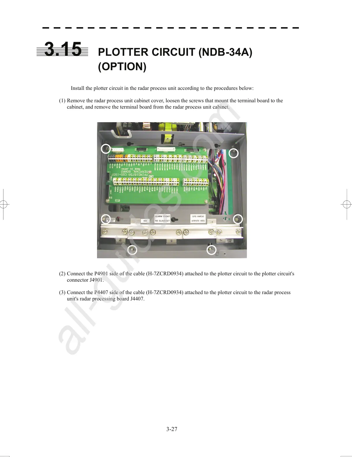
Install the plotter circuit in the radar process unit according to the procedures below:
(1) Remove the radar process unit cabinet cover, loosen the screws that mount the terminal board to the
cabinet, a
n
d remove the terminal board from the radar process unit cabinet.
(2) Connect the P4901 side of the cable (H-7ZCRD0934) attached to the plotter circuit to the plotter circuit's
connector J4
901.
(3) Connect the P4407 side of the cable (H-7ZCRD0934) attached to
the plotter circuit to the radar process
unit's radar processing board J4407.
3-27
All manuals and user guides at all-guides.com
all-guides.com

Table of Contents

Other manuals for JRC JMA-5312-6

Questions and Answers:

Question and Answer IconNeed help?

Do you have a question about the JRC JMA-5312-6 and is the answer not in the manual?

JRC JMA-5312-6 Specifications

General IconGeneral
BrandJRC
ModelJMA-5312-6
CategoryMarine Radar
LanguageEnglish

Related product manuals