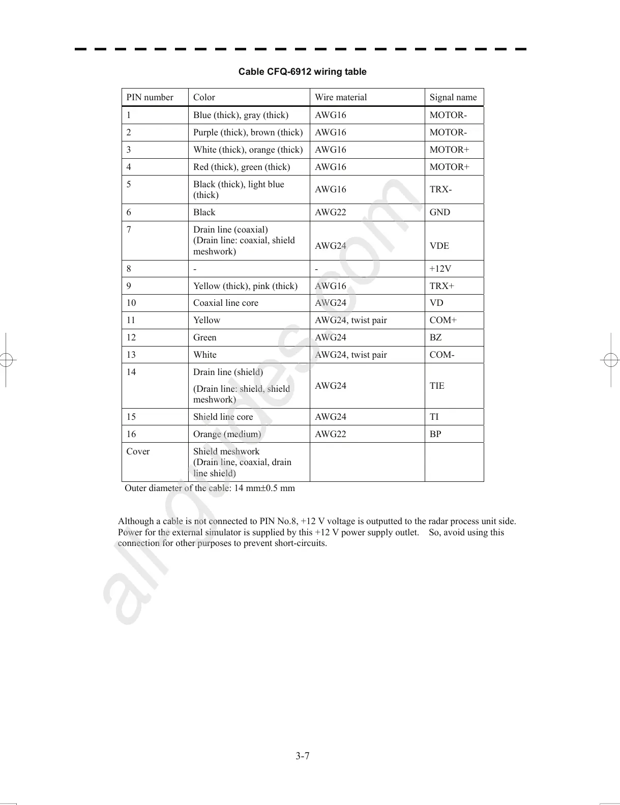
Cable CFQ-6912 wiring table
PIN number Color Wire material Signal name
1 Blue (thick), gray (thick) AWG16 MOTOR-
2 Purple (thick), brown (thick) AWG16 MOTOR-
3 White (thick), orange (thick) AWG16 MOTOR+
4 Red (thick), green (thick) AWG16 MOTOR+
5 Black (thick), light blue
(thick)
AWG16 TRX-
6 Black AWG22 GND
7 Drain line (coaxial)
(Drain line: coaxial, shield
meshwork)
AWG
24
VDE
8 - - +12V
9 Yellow (thick), pink (thick) AWG16 TRX+
10 Coaxial line core AWG24 VD
11 Yellow AWG24, twist pair COM+
12 Green AWG24 BZ
13 White AWG24, twist pair COM-
14 Drain line (shield)
(Drain line: shield, shield
mes
h
work)
AWG24 TIE
15 Shield line core AWG24 TI
16 Orange (medium) AWG22 BP
Cover Shield meshwork
(Drain line, coaxial, drain
line shield)
Outer diameter of the cable: 14 mm±0.5 mm
Although a cable is not connected to PIN No.8, +12 V voltage is outputted to the radar process unit side.
Power fo
r th
e external simulator is supplied by this +12 V power supply outlet. So, avoid using this
connection for other purposes to prevent short-circuits.
3-7
 Loading...


