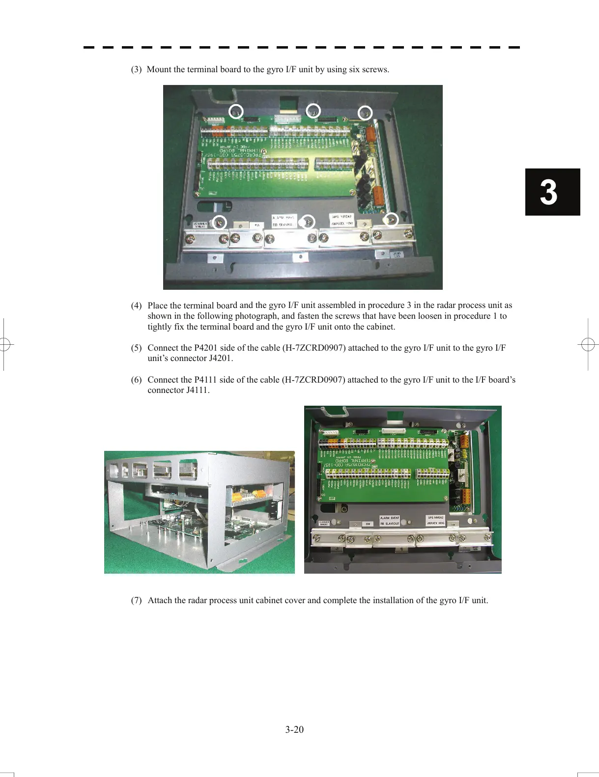
(3) Mount the terminal board to the gyro I/F unit by using six screws.
3
(4) Place the terminal boa
rd and the gyro I/F unit assembled in procedure 3 in the radar process unit as
shown in the following photograph, and fasten the screws that have been loosen in procedure 1 to
tightly fix the terminal board and the gyro I/F unit onto the cabinet.
(5) Connect the P4201 side of the cable (H-7ZCRD0907) attached to the gyro I/F unit to the gyro I/F
u
nit’s connector J4201.
(6) Connect the P4111 side of the cable (H-7ZCRD0907) attached to the gyro I/F unit to the I/F board’s
connector J
4111.
(7) Attach the radar process unit cabinet cover and complete the installation of the gyro I/F unit.
3-20
 Loading...


