Adjustment of the antenna and tag
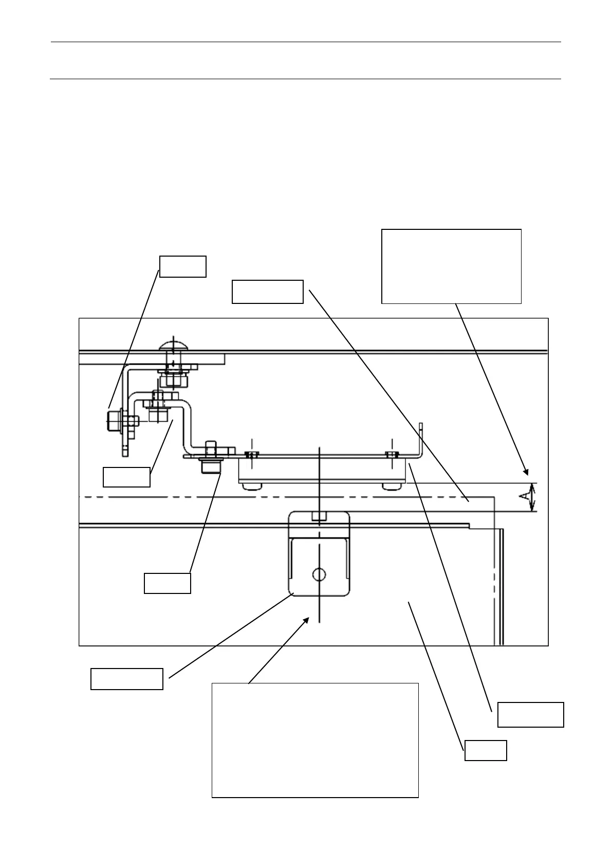
After replacing the antenna, adjust the antenna position as shown in the following figure.
Make an adjustment in the home position where a stop was made by initialization.
When the Z unit goes up and down, no interference must occur among the antenna unit, antenna
unit locking screws, stacker, sensor, and Z unit.
Antenna
Z Unit
Make an adjustment by using
“Screw E” so that the
clearance A between the
sensor tag and the antenna
may be within the range of 2
Make an adjustment by using “Screw F” so
that when the tray is moved to the left and
right according to the stacker play, the
center of the gutter stroke may be matched
with the center of the antenna mark at the
highest-step tray and the lowest-step tray.
Adjust the vertical directions of the sensor
tag and the antenna by using “Screw G.”
4-28