EasyManuals Logo

JUKI TR6SNR User Manual

JUKI TR6SNR
126 pages
To Next Page IconTo Next Page
To Previous Page IconTo Previous Page
Page #34 background imageLoading...
Page #34 background image
Maintenance Guide
3-18
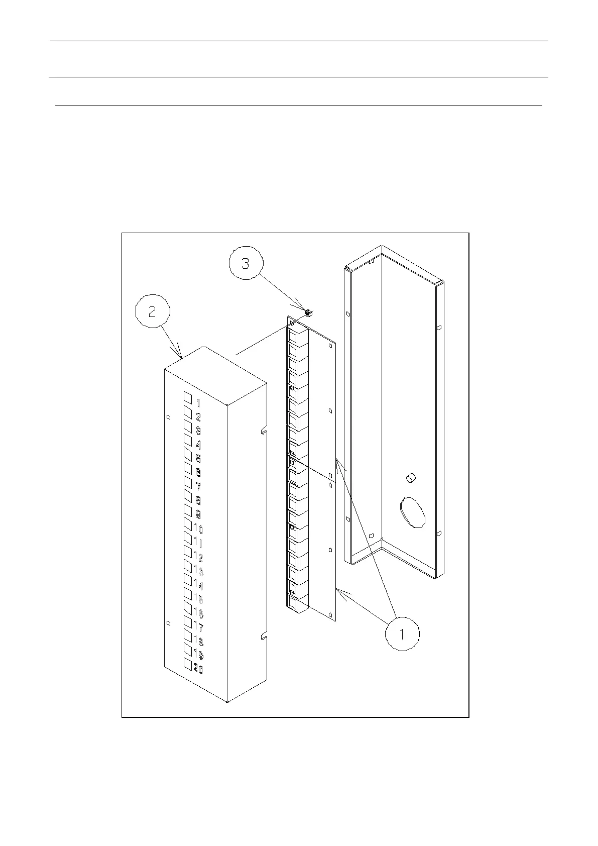
3-11. Replacement of tray LED PCB (option: run-out components indication switch)
Detach the SW BOX R 5D . Then remove the nut of the Tray LED PCB .
When the PCB replacement is finished, jumper setting is required.
To mount PCB on the top stage, make jumper setting on 1 to 5 of W1 and 6 to 10 of W2.
To mount PCB on the bottom stage, make jumper setting on 11 to 15 of W1 and 16 to 20 of W2.
Tray LED (10) PCB ASM (part No.: 40042216)

Table of Contents

Questions and Answers:

Question and Answer IconNeed help?

Do you have a question about the JUKI TR6SNR and is the answer not in the manual?

JUKI TR6SNR Specifications

General IconGeneral
BrandJUKI
ModelTR6SNR
CategoryIndustrial Equipment
LanguageEnglish

Related product manuals