2 Instrument description
20
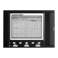
Display Each of the digital signals can be assigned to a digital channel within a group.
They are represented by various diagrams on the screen:
Outputs The digital signals can be used to operate the five relays and the open-
collector output. The action can be configured as break (n.c.) or make (n.o.)
contact (Configuration ➔ Outputs).
Counters The digital signals can be configured as control signals for counters under
Configuration ➔ Control functions ➔ Counters (v Chapter 4 “Configuration
parameters”). If a counter text is configured, it is possible, for example, to
count when and how often a group alarm has been triggered.
External texts External texts can be arranged through the seven logic inputs or the 6 external
inputs. Either a standard text or one of the 146 definable texts can be used.
The instrument automatically supplements the texts in order to distinguish
between the appearance and disappearance of the signal. External texts are
configured on the instrument under Control functions.
v Chapter 3.5 “Event list”
External report/
batches
Start and end of the external report, as well as of the batch report, are
controlled through one of the digital signals. The external report and, if
required, the batch report are run from the instant at which the control signal
becomes active. It is continued until the control signal becomes inactive again.
The control signal is selected through the parameter
Configuration Î Report/batches Î Ext.report/batches Î Control signal.
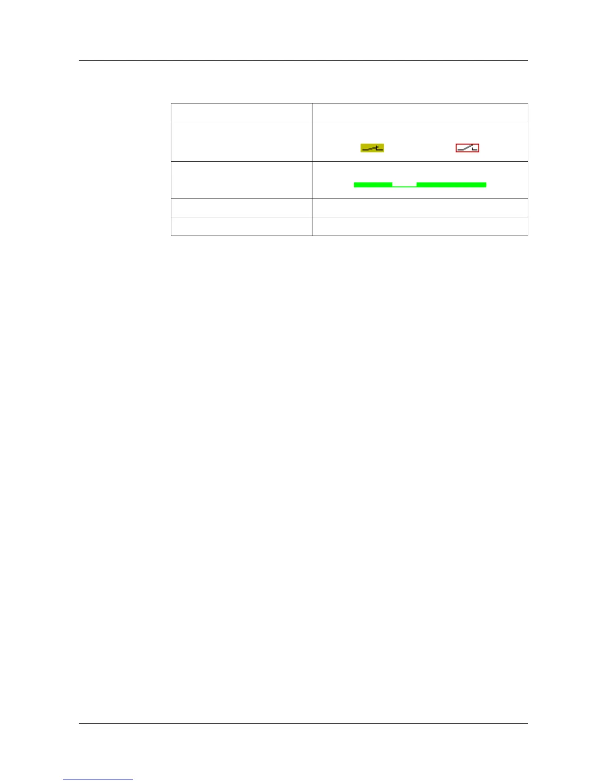
Diagram Representation
Group manager On/off represented as switch:
Horizontal diagram Representation as a record of time:
Bar graph On/off represented as switch
Numerical representation On/off represented as switch