Table 17: T1/E1 Interface Module—RJ-45 Connector Pinout (continued)
SignalRJ-45 Pin
–8
Related
Documentation
CTP2000 T1/E1 Interface Module on page 12•
• CTP2000 FXS and FXO Interface Module Cables and Pinouts on page 45
• CTP2000 Series Console Cable Pinouts on page 58
CTP2000 Serial Interface Module Pinouts
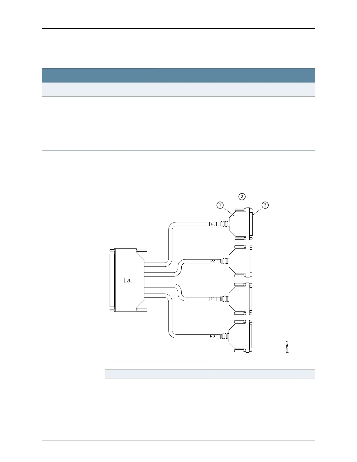
Figure 28 on page 49 displays the serial DCE/DTE cable pin configurations for CTP2000
series devices.
Figure 28: CTP2000 Serial DCE/DTE Cable Pin Configurations
3—1— DB-25 connectorDB-25 shell
2—Thumb screw
Table 18 on page 50 lists the CTP2000 serial DCE cable pinouts.
49Copyright © 2017, Juniper Networks, Inc.
Chapter 6: Cable and Pinout Specifications