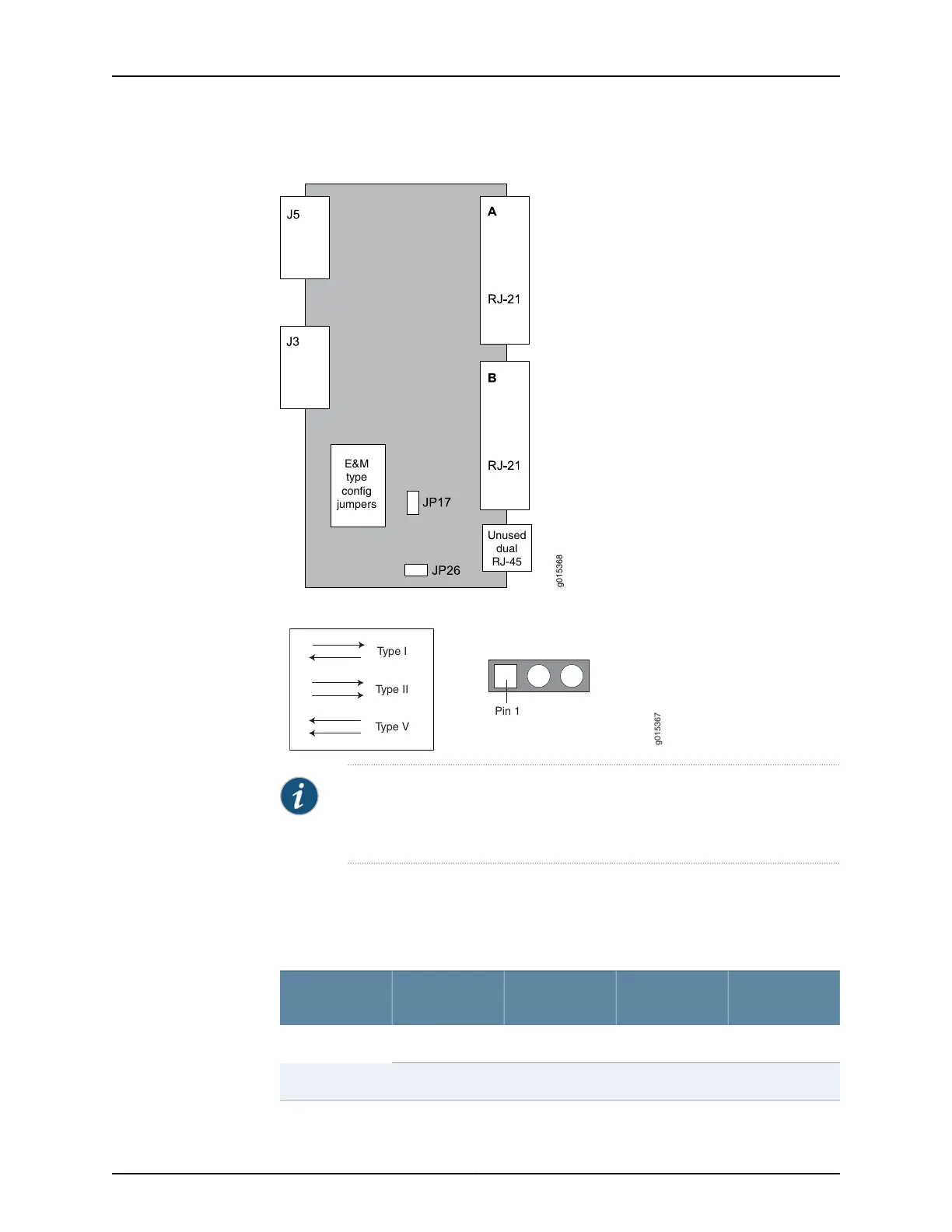
Figure 16: Jumper Locations on the RTM
g015368
E&M
type
config
jumpers
Unused
dual
RJ-45
Figure 17: Jumper Positions for Signaling Types
Pin 1
Type I
Type II
Type V
g015367
NOTE: Jumper JP17 must be in Position 1-2 (see Table 3 on page 15) if any
ports are set for Type II signaling. This jumper ties all signal battery (SB)
signals to battery voltage (–48V).
Jumper JP26 is used to connect all signal grounds (SG) to the chassis ground. When
jumper JP26 is in Position 1-2, the signal ground is connected to the chassis ground. In
Position 2-3, it is isolated from the chassis ground.
Table 3: Jumper Positions for Configuring Port Signaling Type
Signaling Type
V
Signaling Type
II
Signaling Type
IJumper
Position 1-2Position 2-3Position 1-2JP1Port 0
Position 1-2Position 2-3Position 2-3JP9
15Copyright © 2017, Juniper Networks, Inc.
Chapter 2: CTP2000 Series Interface Modules