provides an RS232 serial console via a supplied USB-to-DB9 cable (p/n 720-071594),
in which the DB-9 connector has the same pinout as a standard RS-232 DTE port.
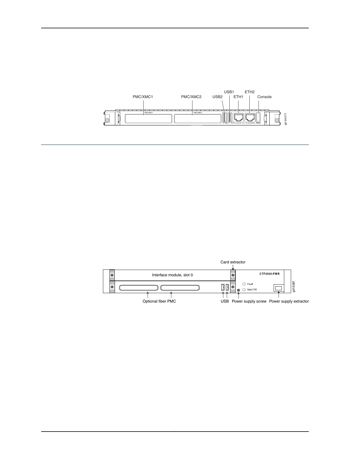
Figure 1: PP833 Processor (AC and DC Version, Front View)
g0 0 9 0 77
PMC/XMC1 PMC/XMC2
2 USB 1 ETH1 ETH2S R U P RS232H
PMC/XMC1 PMC/XMC2
USB1
USB2 ETH1
ETH2
Console
CTP2008 Platform
The Juniper Networks CTP2008 Circuit to Packet platform is a 3-U high, full-rack wide
chassis designed for tabletop or shelf installation. It can also be installed in a rack with
the supplied rack-mounting kit. The CTP2008 platform has one removable interface
module and one removable processor module, and is available in both AC-powered and
DC-powered versions. It has a removable fan tray, and airflow is side-to-side.
Figure 2 on page 4, Figure 3 on page 5, and Figure 4 on page 5 show the CTP2008
chassis containing the PP332 processor (which requires an RTM card for Ethernet and
console port accesses). The new PP833 processor module does not require an RTM card.
All PP833 module access is located on the front panel with all CTP serial and T1/E1 ports.
If you are upgrading from the old PP310 or PP332 processor to the PP833 processor, the
RTM card may be left in the node. But, none of the interfaces (Ethernet or serial ports)
on the RTM panel are functional.
Figure 2: CTP2008 Chassis Containing the PP332 Processor (AC and DC
Version, Front View)
USBOptional fiber PMC
Interface module, slot 0
Card extractor
Power supply screw Power supply extractor
g015387
The front panel comprises the following components (see Figure 2 on page 4):
•
Interface module—Frame processing and forwarding engines.
•
Processor module—Two slots are available on this module for an optional fiber Gigabit
Ethernet or Fast Ethernet PMC module. The primary SC connector is on the left side.
•
Power supply extractor—Push the button to eject the power supply module.
The rear panel (RTM) comprises the following components (see Figure 3 on page 5 and
Figure 4 on page 5):
•
PMC I/O—Both PMC slots are available to support compatible PMC I/O modules.
•
Clock module—Provides clock distribution between modules when the backplane is
in use by voice applications.
Copyright © 2017, Juniper Networks, Inc.4
CTP2000 Hardware Documentation