processor, the RTM card may be left in the node. But, none of the interfaces (Ethernet
or serial ports) on the RTM panel are functional.
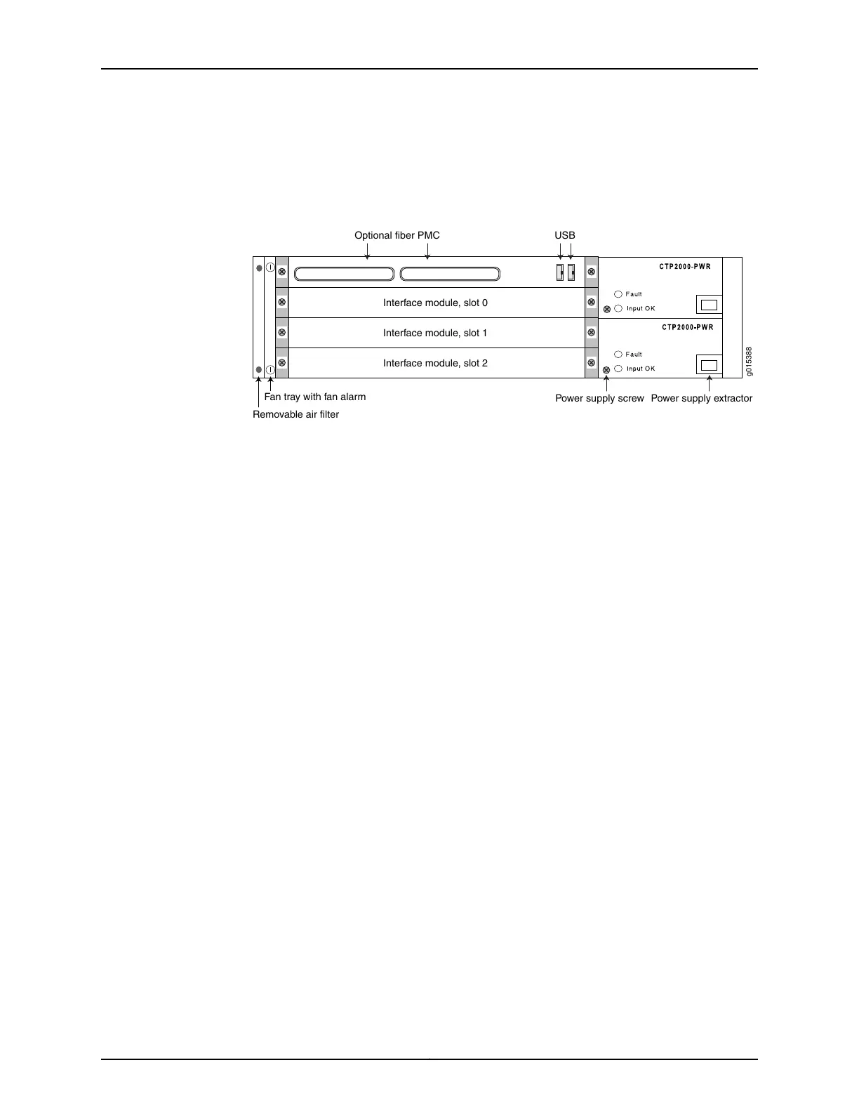
Figure 5: CTP2024 Chassis Containing the PP332 Processor (AC and DC
Version, Front View)
USB
Optional fiber PMC
Power supply screw Power supply extractor
Interface module, slot 0
Fan tray with fan alarm
Removable air filter
Interface module, slot 1
Interface module, slot 2
g015388
The front panel comprises the following components (see Figure 5 on page 6):
•
Interface modules—Frame processing and forwarding engines.
•
Processor module—Two slots are available on this module for an optional fiber Gigabit
Ethernet or Fast Ethernet PMC module. The primary SC connector is on the left side.
•
Power supply extractor—Push the button to eject the power supply module.
•
Fan tray and air filter.
The rear panel (RTM) comprises the following components (see Figure 6 on page 7
and Figure 7 on page 7):
•
PMC I/O—Both PMC slots are available to support compatible PMC I/O modules.
•
Clock module—Provides clock distribution between modules when the backplane is
in use by voice applications.
•
Power supply—Use a standard IEC power cord for the AC version. Use a 22-AWG fork
terminal connector for the DC version. Power redundancy is supported for the AC
version and the DC version. A single IEC power cord is used to connect the redundant
AC power supply modules, which keeps the chassis turned on in the event of failure of
one of the power supplies.
There are no power switches on CTP2000 Series DC models, so a readily accessible
disconnect device must be provided as part of the electrical installation of the unit.
We recommend the 22-AWG wire for DC power terminals.
•
Ethernet connection—Provides the 1-Gbps Ethernet connection to the IP network by
means of a local Ethernet switch or router.
•
Console connection—Provides an asynchronous tty connection for locally configuring
the CTP Series device. On the PP310 and PP332 processors, you can connect a console
directly to the COM2 port (which is an RJ-45 type connector) found on the RTM panel.
Copyright © 2017, Juniper Networks, Inc.6
CTP2000 Hardware Documentation