Related
Documentation
Installing a CTP Interface Module, Processor Module, or Clock Module on page 89•
Installing a PMC on CTP2000 Platforms
The PCI mezzanine card (PMC) is mounted on the processor module and can be installed
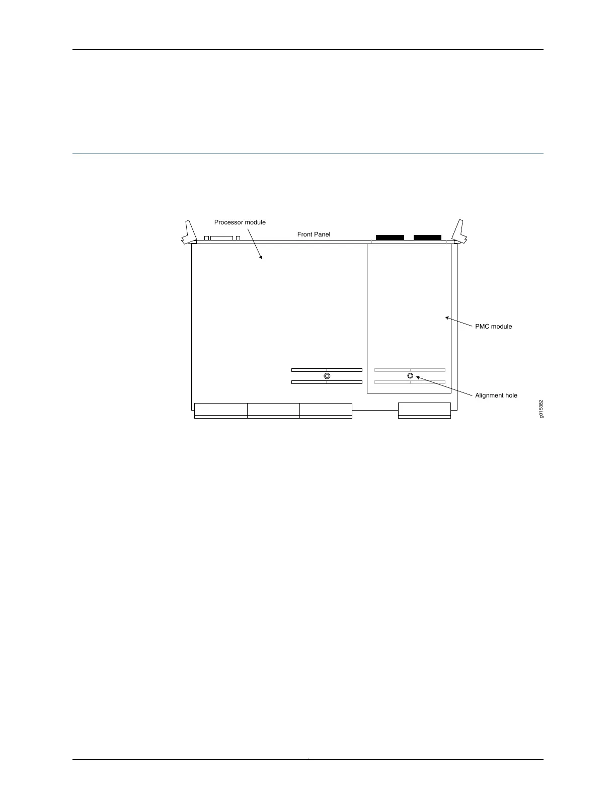
or replaced in the field. Figure 36 on page 92 displays the location of the PMC.
Figure 36: CTP2000 Platforms PMC Location
Processor module
PMC module
Alignment hole
Front Panel
g015382
To install a PMC:
1. Confirm that the device is powered off.
2. Remove the processor module by unscrewing the retaining screws and pushing the
extractors outward while depressing the latching buttons.
3. If a PMC was not previously installed, a shield may have been inserted in the PMC slot
of the processor’s front panel. Remove this shield by gently pushing it out from behind
the panel.
4. The PMC has four screws. Two of the screws are secured to standoffs, and two are
attached to the front assembly of the PMC. Remove the two screws secured to the
standoff, leaving the standoff attached to the PMC. Remove the two screws on the
front assembly located on the side with the standoffs. The front assembly should
remain attached to the PMC hardware. Keep the screws for reattachment.
5. Align the PMC with the printed circuit board connectors toward the processor board
and with the fiber connectors inserted through the processor’s front panel. Align the
alignment post on the processor module with the PMC’s alignment hole.
6. Gently press the PMC into the processor module.
7. From the back of the processor module, use the four Phillips head screws to secure
the two PMC standoff posts and PMC front assembly to the processor module.
8. Reinstall the processor.
Copyright © 2017, Juniper Networks, Inc.92
CTP2000 Hardware Documentation