Geode GNS3 Real-Time Sub-Meter GPS Receiver
154 Appendix A Serial Port Configuration
10. Appendix A: Serial Port
Configuration
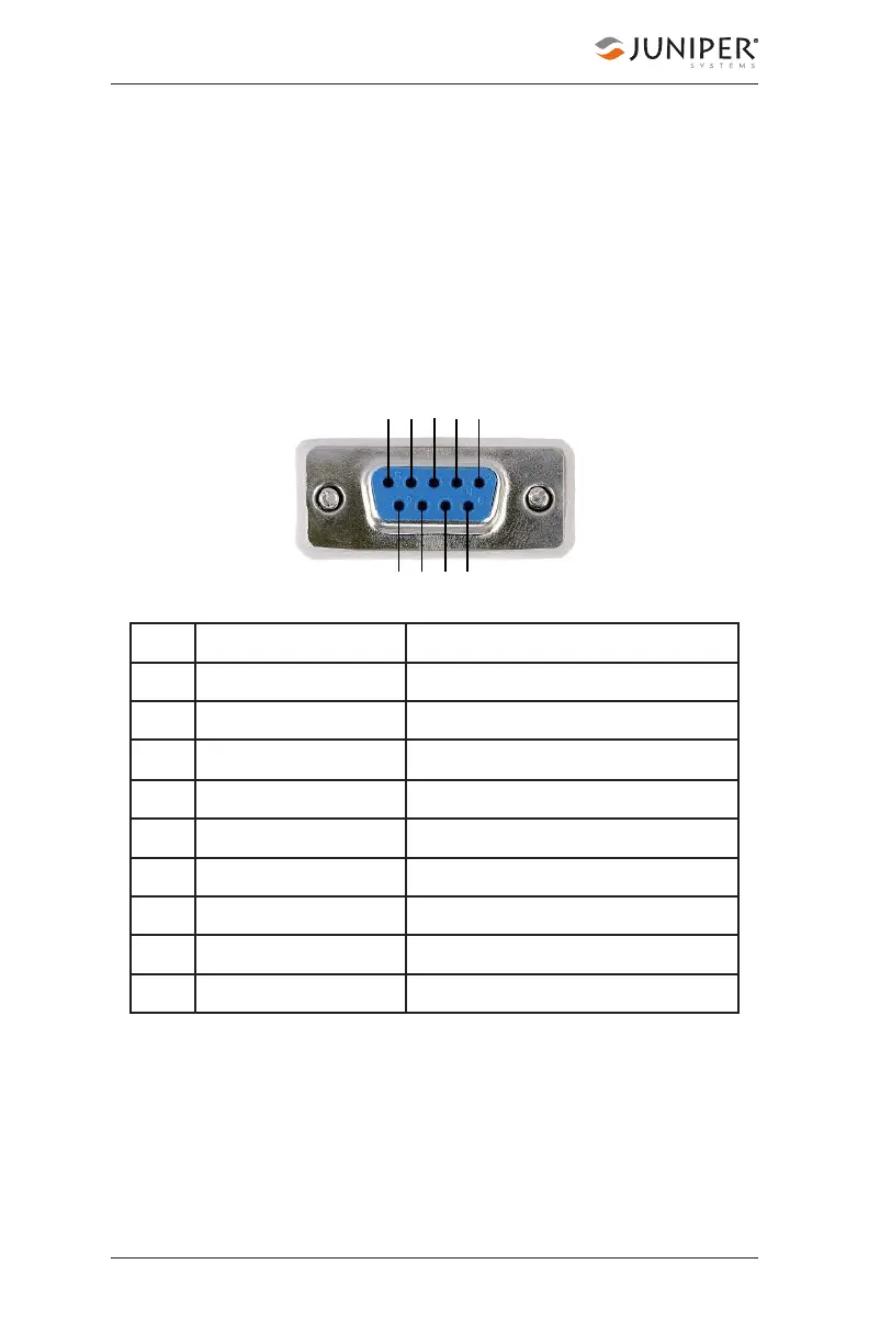
The Geode has a 9-pin RS-232C serial port. This allows the
Geode to be mounted to a piece of equipment such as a
tractor or a precision planter. This type of configuration
maintains a constant connection for data and power to the
Geode. Use a straight-through 9-pin cable to establish
communication between the Geode and your mobile
device. The functions of each pin are listed below.
You can remotely power on and off the Geode through pin
9 of the serial connection. Apply or remove 12 V (nominal) to
cycle power on the Geode.
Pin Signal Condition
1 PPS output Normally low, pulsing high
2 TXD out
3 RXD in
4 Event Mkr in High to mark
5 GND
6 GPS Lock out High indicates GPS lock
7
8 Speed Pulse out Normally low, pulsing high
9 +12V in