1-5
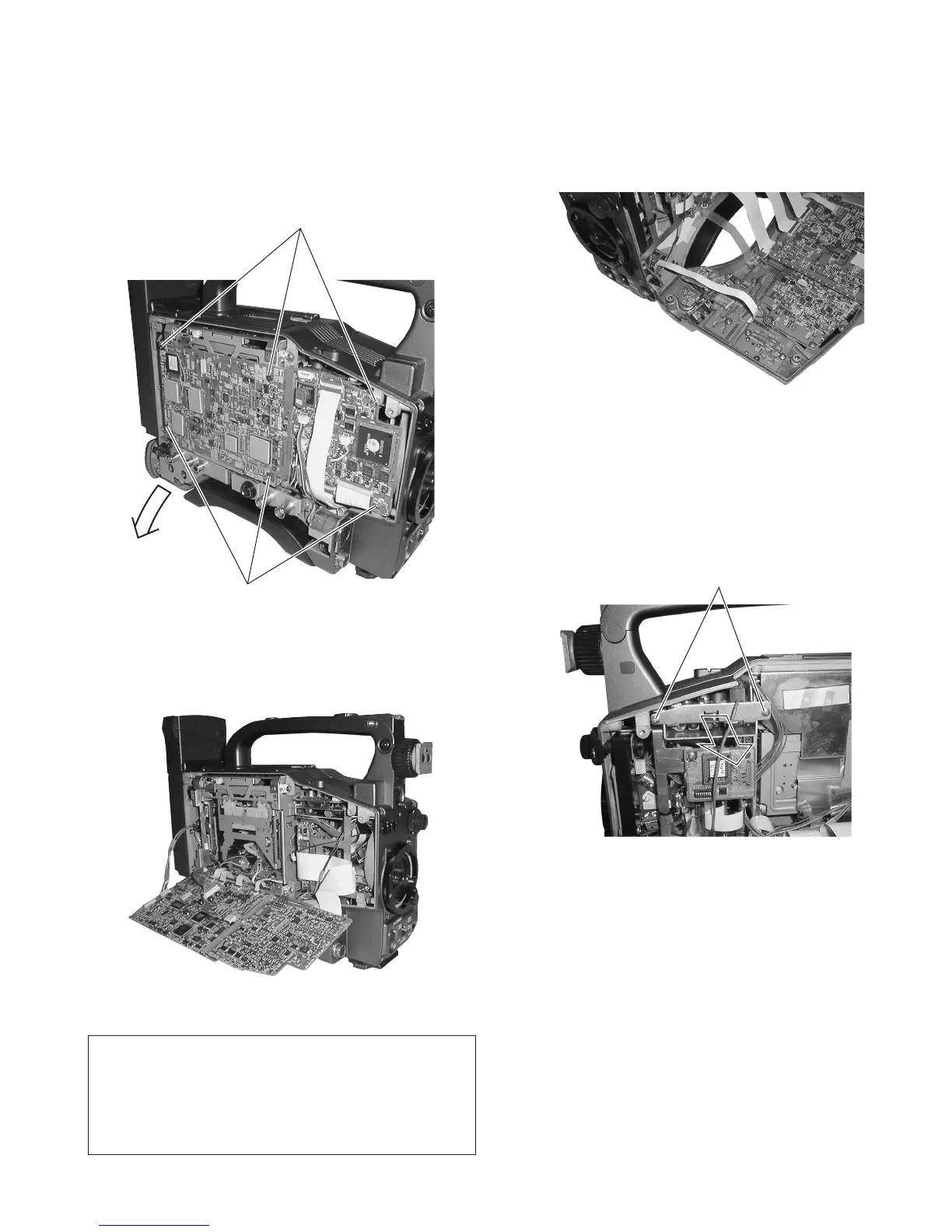
1.5.2 Removing the CAM1 Board
(1) Remove the left side cover (section 1.2.1).
(2) Remove the 6 screws
2
.
(3) The DV MAIN board on the VCR side and the CAM2 board
are connected by a board-to-board connector. Open the two
boards together in the direction of the arrow.
Fig. 1-5-4
1.5.4 Removing the PS 1 & 2 board.
(1) Open the right side cover (see section 1.2.2).
(2) Remove the 2 screws
3
retaining the PS 1 & 2 board.
(3) Pull out the PS 1 & 2 board, along the guide rail in the direc-
tion of the arrow.
Fig. 1-5-3
1.5.3 Removing the SW Boards
(1) Open the right side cover (see section 1.2.2).
(2) The JOG, SWRU, SWRM, SWPW and SWRB boards are
attached on the right side cover. Remove them as required.
Fig. 1-5-2(2)
(4) The opened boards can be secured by fitting them into the
notches on the VCR side frame as shown in the figure.
Fig. 1-5-2(1)
2
2
3
The operation of the VCR can be confirmed when the
circuit boards are tilted.
When the circuit boards are tilted, take care that the
electrical circuitry on each board is not short-circuited
by the BNC connector located below the board.

 Loading...


