2-10
1
2
3
4
Part Name
Å
Cassette housing assembly,
ı
Main deck assembly
1
Drum assembly
2
Motor bracket assembly
3
Middle catcher assembly
Symbol
S
W
P
*
2.6
DISASSEMBLY/ASSEMBLY OF MECHANISM ASSEMBLY
2.6.1
Assembly/Disassembly
The following table shows the mechanism assembly/disassem-
bly procedures.
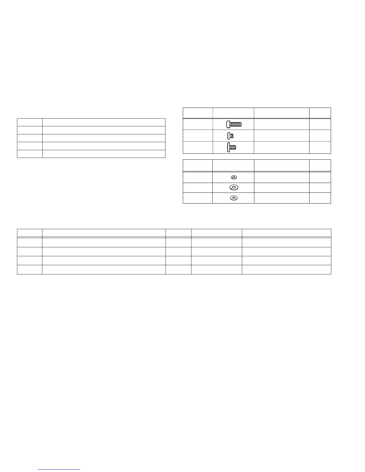
2.6.2 Screws and Washers Used in Mechanism Assembly
Disassembly/Assembly
Table 2-6-1 shows the symbols, designs, part numbers and colors
of the screws and washers used with the Mechanism assem-
bly.
When disassembling or assembling the Mechanism assembly,
be sure to attach the correct screws and washers by referring
to the following table.
W1
W3
YQ44246
YQ43933-2
W2
YQ44246-3
(S1)
(S2)
(S3)
QYSDSP2005Z
YQ43893-7
YQ43893
Symbol
Symbol
Design
Design Part No.
Part No.
Color
Red
Black
Black
Color
Gold
Silver
Black
1
: Names of the disassembled/assembled parts.
2
: Items of disassembly.
3
: Parts to be removed for disassembly, such as screws, wash-
ers and springs, and points.
Name or Point
Screw
Washer
Spring
Connector, lock (L), soldering (SD), shield, etc.
Step
1
2
2
3
Points
2(S1), (L1) to (L5)
3(S2)
4(S2)
3(S2)
Remark
↑
1
↑
2
↑
3
Fig. 2-6-1
2-9

 Loading...


