1-4
(9) Remove the 4 screws
5
and separate the optical block as-
sembly from the front panel.
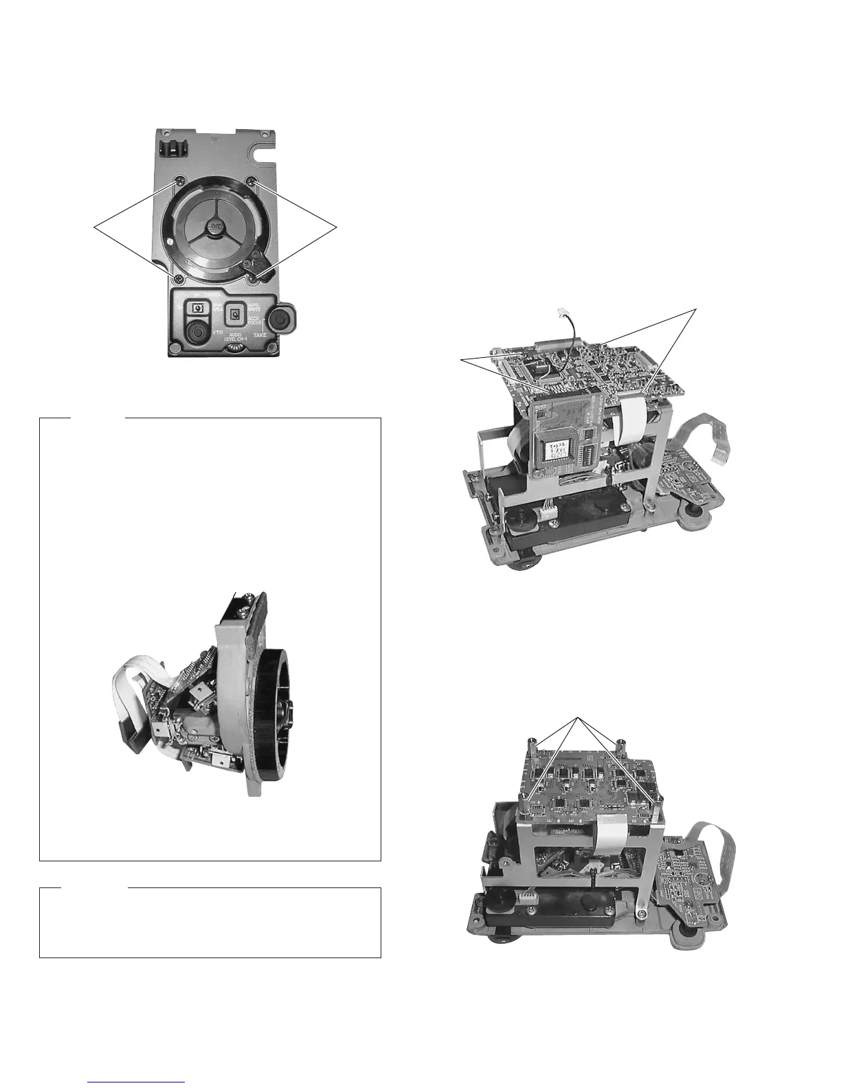
1.5 REMOVING MAJOR BOARDS FROM THE
CAMERA
1.5.1 Removing the CP and TG Boards.
(1) Remove the right side cover (see section 1.2.2).
(2) Remove the 4 screws retaining the front panel (see section
1.4.3).
(3) Pull out the optical block assembly and the front panel to-
gether toward the front.
(4) Remove the screw retaining the ROM board. Now the ROM
board can be removed.
(5) Remove the 4 screws
1
. Now the CP board can be removed.
Fig. 1-4-6 Optical Block Assembly for Servicing
Fig. 1-4-5
Fig. 1-5-1(2)
(6) Remove the CP board, then remove the 4 stud screws
4
.
Now the TG board is disengaged from the stay.
(7) Unplug the flexible cables connecting the IS boards and the
TG board. Now the TG board can be removed.
Fig. 1-5-1(1)
CAUTION
When mounting the optical block assembly in the camera,
take care of the positioning of the wire assembly. A malfunc-
tion may occur if a wire is somehow caught up.
55
NOTES
• The CCDs are bonded precisely to the prism. In case of
trouble with a CCD, it is not possible to replace an indi-
vidual CCD, but the entire optical block assembly should
be replaced.
• The optical block assembly supplied as a service part
(SCM1049-N0A (NTSC)/P0A (PAL)) is not equipped with the
DR board. When replacing the optical block assembly, at-
tach the surrounding PC boards to the new assembly be-
fore mounting it in the camera.
1
1
4

 Loading...


