2-3
2.2
BASICS OF MECHANISM DISASSAMBLY/ASSEMBLY
2.2.1 Assembly mode
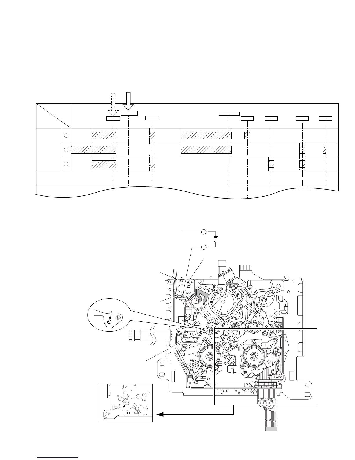
The disassembly and assembly of the mechanism can be done
in the ASSEMBLY mode (see Table 2-2-1).
The ASSEMBLY mode is provided in the intermediate position
between C-IN and S.FF. As the C-IN (Cassette IN) mode is usu-
ally set when a cassette tape is ejected, the ASSEMBLY mode
should be entered after entering the C-IN mode. To set the AS-
Fig. 2-2-1
Table 2-2-1
SEMBLY mode, apply 3 V DC to the electrodes at the top of the
loading motor shown in Fig. 2-2-1. The ASSEMBLY mode is set
when the markings (red) on two gear teeth of the rotary en-
coder are aligned with the confirmation holes.
R. ENC -20
ROTARY
ENCORDER
2
1
3
MAIN CAM GEAR 0
C-IN
ASSEMBLY
S. FF
LOADING END
PLAY REV STOP FF/REW
0
15
33.33
40
166.66
140
193.33
160
226.66
185
273.33
220
306.66
245
36°
17°
169.66°
87°
190.33°
196.33°
223.66°
229.66°
270.33°
276.33°
303.66°
30.33°
36.33°
MODE
PARTS
H
C
< ASSEMBLY MODE >
Back side of Mechanism assembly
The ASSEMBLY mode is set
according to the markings
(colored red) on two gear teeth
of the rotary encoder.
Note:
Marking
(colored red)
Wire (Red)
Wire (Brown)
Rotary encoder
Motor bracket assembly (Loading motor)
2-2

 Loading...


