2-13
No.
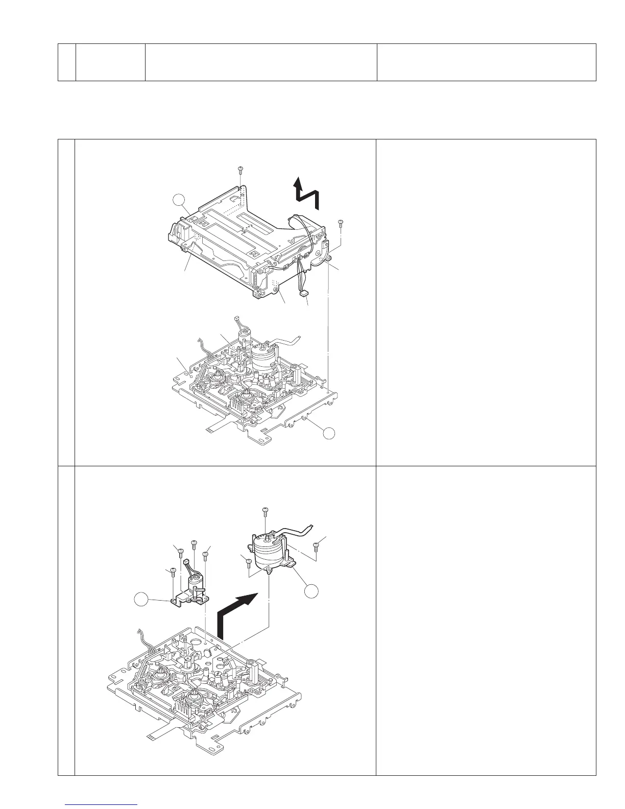
Item Reference picture/drawing Procedure
1
Å
Cassette housing assembly
2
1
Drum assembly,
2
Motor bracket assembly
2.7 REPLACEMENT OF MAJOR PARTS
⋅ Make sure that the mechanism is in the ASSEMBLY mode before proceeding to disassembly or assembly. (See section 2.1,
“Assembly Mode”.)
⋅ Screws must always be tightened using a torque screwdriver and at the specified torque.
<Removal>
1
Drum assembly
1)Remove the 3 screws (S2) and take out the as-
sembly.
2
Motor bracket assembly
1)Remove the 4 screws and take out the motor
bracket assembly.
<Attaching>
1) Reverse the removal procedure
<Removal>
1)Remove the 2 screws (S1) then take out the cas-
sette housing by sliding it upward and toward the
front.
<Attaching>
1)Reverse the removal procedure.
Fig. 2-7-1
1
(
S1
)
A
2
(
S1
)
(
L2
)
(
L4
)
(
L5
)
(
L1
)
(
L3
)
B
Note 1
5
(
S2
)
1
2
3
(
S2
)
4
(
S2
)
7
(
S2
)
6
(
S2
)
9
(
S2
)
8
(
S2
)
Fig. 2-7-2
2-12

 Loading...


