3-6
No. Item
Measuring
instruments &
Input signals
Mode
Measuring point
(*)
Adjustment parts
(-)
Adjustment level
(+)
Adjustment procedure
3-5
3.5 CAMERA ADJUSTMENTS
3.5.1 SSG Adjustment
1
fh frequency
adjustment
• Frequency
counter
Adjustment
menu 1/6
(Color bar
output)
* TP101 (CAM2)
- SHUTTER/MENU
dial
+ 27 MHz ±30 Hz
(1) Open the left side cover.
(2) Rotate the SHUTTER/MENU dial to select
MENU 1/6: FH.
(3) Push the SHUTTER/MENU dial so that the ad-
justment value blinks then rotate it to adjust to
the specified level.
(4) Push the SHUTTER/MENU dial to store the
adjustment data in memory.
HFO
ET ST OUT LEVEL : O
C– AMERA ADJ UST MENU– 1 / 6
1
TEST OUT
LEVEL
adjustment
• Oscilloscope
(H-rate, 10:1)
or WFM
Adjustment
menu 1/6
(Color bar output)
* TEST OUT
(75 Ø terminated)
- SHUTTER/MENU
dial
+ 1 Vp-p ± 0.003 Vp-p
(140 IRE ±4 IRE)
(1) Rotate the SHUTTER/MENU dial to select
MENU 1/6: TEST OUT LEVEL.
(2) Push the SHUTTER/MENU dial so that the ad-
justment value blinks then rotate it to adjust to
the specified level.
(3) Push the SHUTTER/MENU dial to store the
adjustment data in memory.
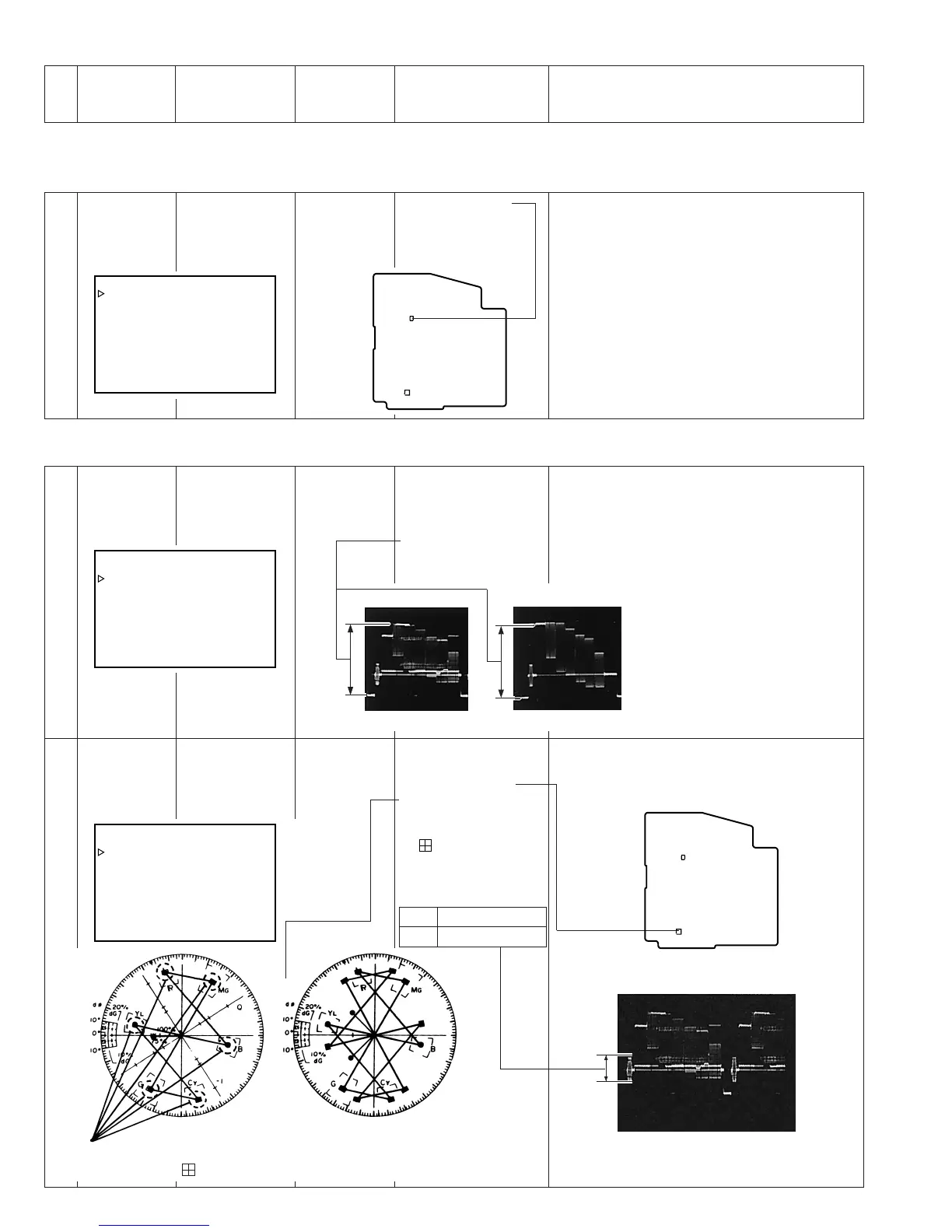
3.5.2 Encoder Adjustments
HFO
ET ST OUT LEVEL : O
C– AMERA ADJUST MENU– 1 / 6
2
CHROMA
LEVEL
adjustment
• Oscilloscope
(H-rate, 10:1)
or WFM
• Vectorscope
Adjustment
menu 1/6
(Color bar
output)
* TEST OUT
(75 Ø terminated)
- VR801 (CAM2)
+ All the spots of the
color bar signal
should be within the
marks of the
vectorscope and the
burst level should be
as specified.
(1) Open the left side cover.
(2) Adjust VR801 on the CAM2 board to the speci-
fied level.
HFO
ET ST OUT LEVEL : O
C– AMERA ADJUST MENU– 1 / 6
TP101
VR801
TP101
VR801
CAM2 board
Adjust so that all the spots are
located inside the marks.
NTSC PAL
NTSC 0.286 ± 0.015 Vp-p
PAL 0.3 ± 0.015 Vp-p
[PAL][NTSC]
CAM2
board

 Loading...


