1-12
1.9 CAUTION FOR REPLACING THE DV MAIN BOARD
AND VIDEO SYSCON BOARD
When the DV MAIN board or VIDEO SYSCON board has been
replaced for servicing, be sure to enforce the following items.
1.9.1 DV MAIN Board
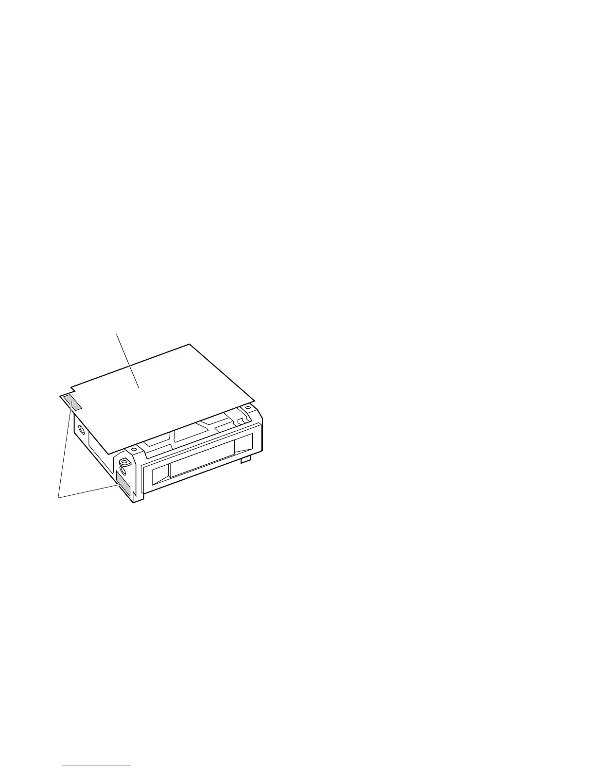
[A] About the ID Management Label
Each VCR unit carries an ID label in compliance with IEEE1394
showing the unique ID assigned on the production line.
(See the following figure for the label position.)
When replacing the DV MAIN board, remove the ID manage-
ment label that was provided originally with the unit from the
defective board and attach it in the same position to the new
board.
[B] Load EEPROM Internal Data
The EEPROM provided with the new board for replacement
contains no data, while the EEPROM originally provided with
the VCR unit contains the IEEE1394 ID data as well as all adjust-
ment data written in the assembly and adjustments written on
the production line. This means that the new VCR unit will not
function if the new EEPROM is used in the condition in which it
is delivered.
When replacing the DV MAIN board, load the internal data of
the EEPROM on the original board to the EEPROM of the new
board.
(1) How to use original EEPROM to new DV MAIN board.
Remove the EEPROM from the original DV MAIN board,
and attach the chip to the new board.
(2) How to write data from the original board to the new
EEPROM
How to load all parameters in EEPROM on original board to
new EEPROM by using the adjustment software.
(For details, see section 3.7.13)
(3) In case of original EEPROM on the original DV MAIN board
was broken.
Load the default data before making adjustments with the
adjustment software, write the data in the new EEPROM,
then make adjustments by following the adjustment proce-
dures. (See section 3.7.12 for details.)
And then, input the ID number on the original board to new
EEPROM by using the adjustment software. (See section
3.7.13 for details.)
Fig. 1-9-1
DV MAIN board
ID Label
1.9.2 VIDEO SYSCON Board
[A] Transporting of IC407 (EEPROM) Data
When the SSF function is used, the cassette number recorded
on tape (see section 9.4.1) has the model ID code appended to
it. The model ID code is written in IC407 (EEPROM). However,
as the new EEPROM mounted on the new replacement circuit
board does not have the ID code written into it, the SSF func-
tion cannot work normally (the model ID code should be written
in IC407 for the correct operation of the SSF function).
Nevertheless, no means is provided for transporting the model
ID code from the original EEPROM to the new EEPROM. There-
fore, it is recommended to remove the original IC from the origi-
nal board and mount it on the new board.
[B] ID Management Label
An ID management label is attached to the camera head. For
the position, see Fig. 1-4-1.

 Loading...


