1-11
1.8.3 Manual Tape Ejection
If the loading motor cannot be run by the procedure outlined in
section 1.8.2, the mechanism may be defective. When the load-
ing motor is defective, remove the tape as described below.
(1) Remove the mechanism unit from the main unit. See sec-
tion 1.6.2 for the removal method.
(2) After removing the mechanism unit, remove the DV MAIN
board (see section 1.6.3).
(3) Remove the 2 screws and remove the active head cleaner
assembly (see section 1.7.2).
(4) Remove the side cover to easy operation (see section 1.7.2).
(5) Remove the 2 screws and remove the rear panel from the
side of the PR & MDA board.
Carefully unplug the wires so as not to damage them, then
remove the PR & MDA board (see section 1.7.2).
(10) The pole base assemblies should be unloaded little by lit-
tle. If they are returned completely beyond the position of
the tape, the tape may slacken and become damaged or
stained by grease.
(11) If the tape slackens, take it up by rotating the shaft on the
top of the capstan motor in the direction of the arrow us-
ing a sharp-tipped object (chip IC replacement tool, etc.)
(see section 1.8.2-(4)).
(12) Repeat steps (9) and (10) above until the tape is taken up
completely.
(13) After confirming that the tape has been taken up com-
pletely, tighten the cassette housing retaining screws which
were loosened in step (6).
(14) Attach and clamp the cassette housing again, then rotate
the gear of the housing assembly in the direction of the
arrow to eject the cassette tape in the same way as in
section 1.8.2-(6).
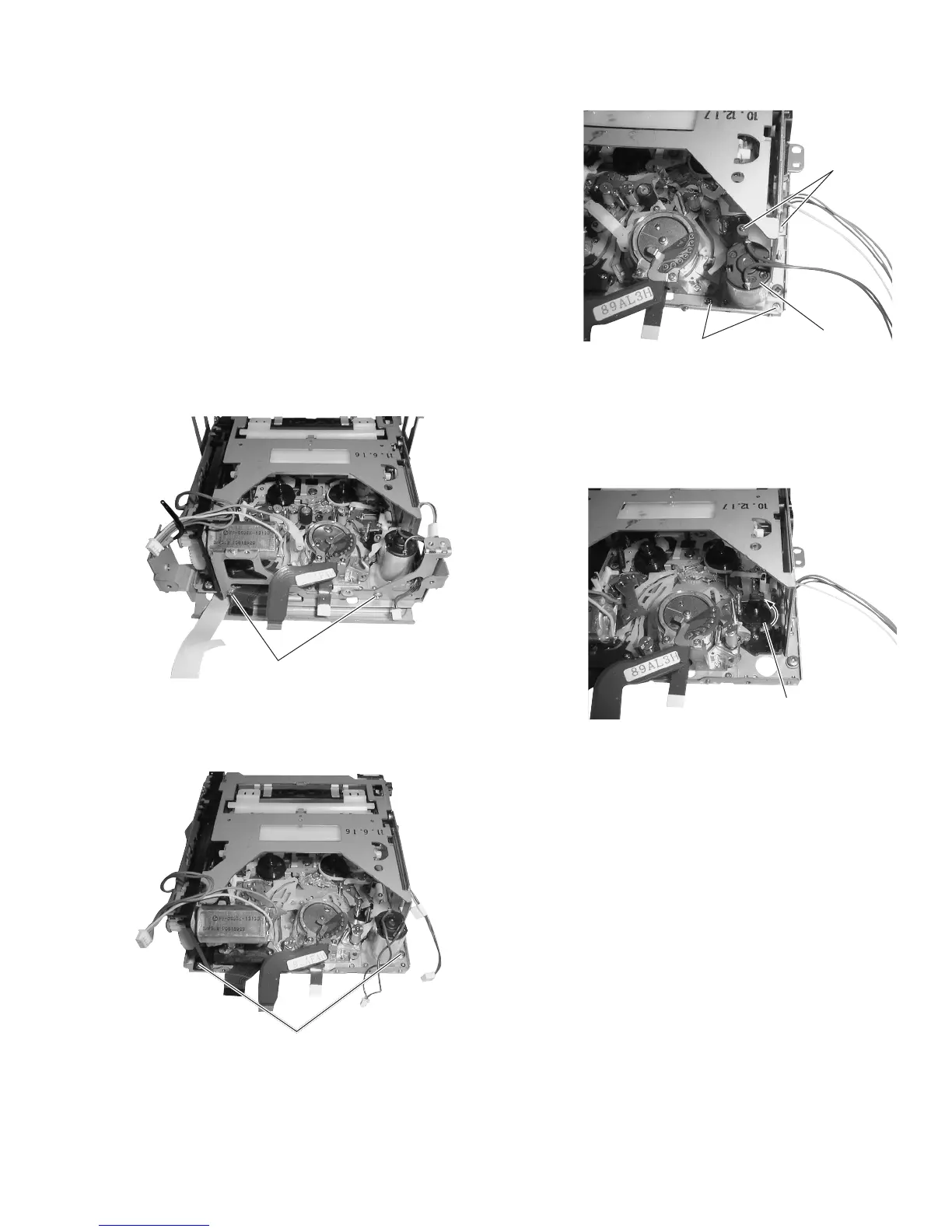
Fig. 1-8-3(4)
Fig. 1-8-3(3)
(9) Unload the pole base assemblies by rotating the gear shown
in the figure in the direction of the arrow.
Fig. 1-8-3(2)
(7) Loosen the 2 screws
2
so that the cassette housing is sepa-
rated freely.
(8) Remove the 4 screws
3
and remove the loading motor.
Fig. 1-8-3(1)
(6) Remove the 2 screws
1
and remove the active head cleaner
stay.
1
2
3
3
Loading motor
Gear

 Loading...


