1-3
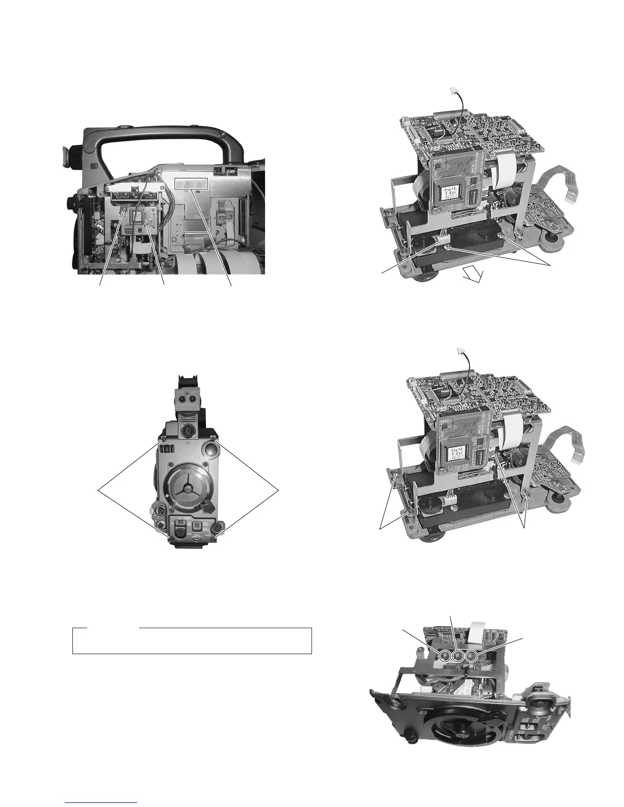
1.4 REMOVING THE OPTICAL BLOCK ASSEMBLY AND
THE OPTICAL FILTER ASSEMBLY
(1) Remove the right side cover (see section 1.2.2).
(2) Remove the screw
1
retaining the ROM board.
Fig. 1-4-4(1)
Fig. 1-4-4(2)
(7) Remove the 4 screws
4
and remove the TG board and CP
board mounting brackets.
(8) Flip open CN11, CN12 and CN13 and unplug the flexible
cables.
Fig. 1-4-3
(5) Loosen the 2 screws
3
and remove the connector
Å
.
(6) Remove the optical filter assembly in the direction of the
arrow.
(4) Pull out the optical block assembly and the front panel to-
gether toward the front.
Fig. 1-4-2
(3) Remove the 4 screws
2
.
Fig. 1-4-1
CAUTION
Be careful not to damage the boards or the FC cables.
1
ROM board
S.S.F. ID label
for VIDEO/SYSCON board
2
4
4
CN11
CN12
CN13

 Loading...


