1-6
4
4
5
Å
ı
Fig. 1-6-2(2)
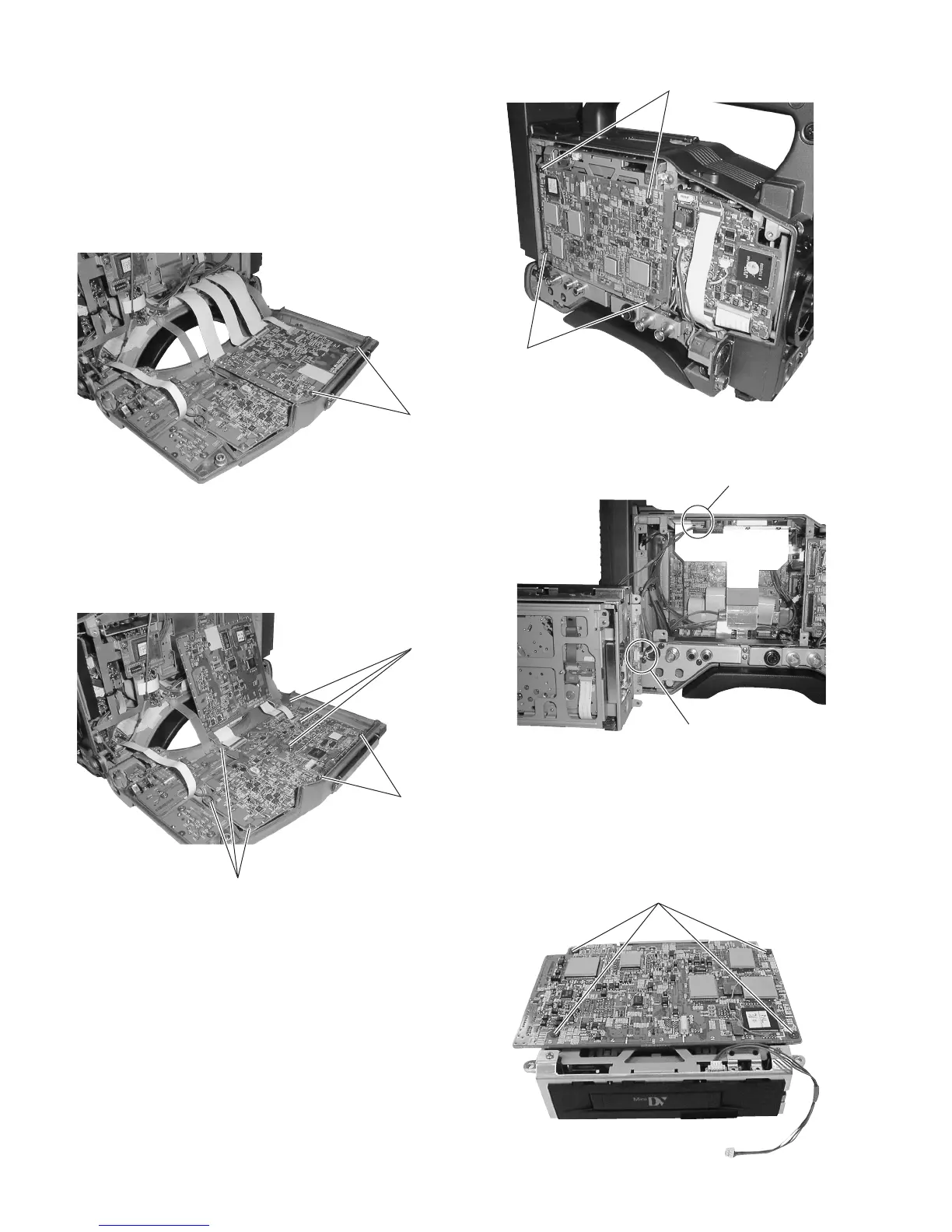
1.6 REMOVING THE MAJOR BOARDS FROM THE VCR
1.6.1 Removing the VIDEO/SYSCON Board and Audio/
LCD Board
(1) Open the right side cover (see section 1.2.2).
The VIDEO/SYSCON board is clamped to the right side cover.
(2) Remove the 2 screws
1
. Now the VIDEO/SYSCON board
can be removed.
Fig. 1-6-1(1)
(3) After removing the VIDEO/SYSCON board, remove the 6
screws
2
and 2 studs
3
. Now the AUDIO/LCD board can
be removed.
Fig. 1-6-1(2)
1.6.2 Removing the VCR Unit
(1) Remove the left side cover (see section 1.2.1).
(2) Remove the 4 screws
4
.
(3) Pull out the VCR unit gently in the direction of the arrow. As
the VCR unit is connected to the CAM2 board with a board-
to-board connector, disconnect it gently.
Fig. 1-6-3(1)
1.6.3 Removing the DV MAIN Board
(1) Remove the VCR unit (see section 1.6.2).
(2) Remove the 4 screws
5
.
(3) Now the DV MAIN board can be removed.
Fig. 1-6-2(1)
(4) Remove the EJECT switch wire
Å
and power supply wire
ı
.
1
3
2
2

 Loading...


