1-7
2
1
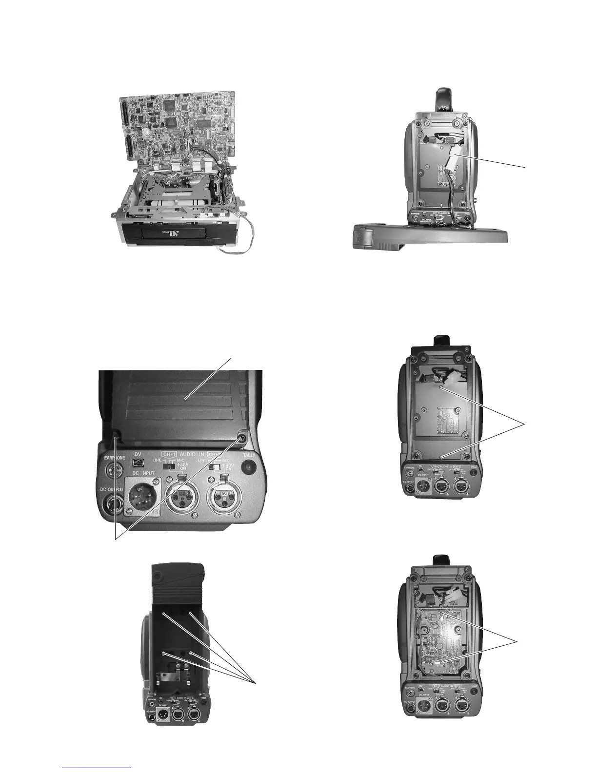
Rear cover
(4) After removing the DV MAIN board, leave it standing up by
fitting it into the notches on the unit frame, as shown in the
figure.
Fig. 1-6-3(2)
(3) Unplug the power cable that supplies power from the bat-
tery case to the main unit, from the connector
Ç
.
Fig. 1-6-5(2)
(3) Remove the 2 screws
4
and remove the REG board.
Fig. 1-6-5(1)
1.6.5 Removing the REG Board
(1) Remove the battery case (see section 1.6.4).
(2) Remove the 2 screws
3
and remove the panel.
1.6.4 Removing the Battery Case
(1) Remove the 2 screws
1
and remove the rear cover of the
battery case.
(2) Remove the 4 screws
2
and remove the battery case from
the main unit.
Fig. 1-6-4(1)
Fig. 1-6-4(2)
Fig. 1-6-4(3)
Ç
3
4

 Loading...


