1-8
4
3
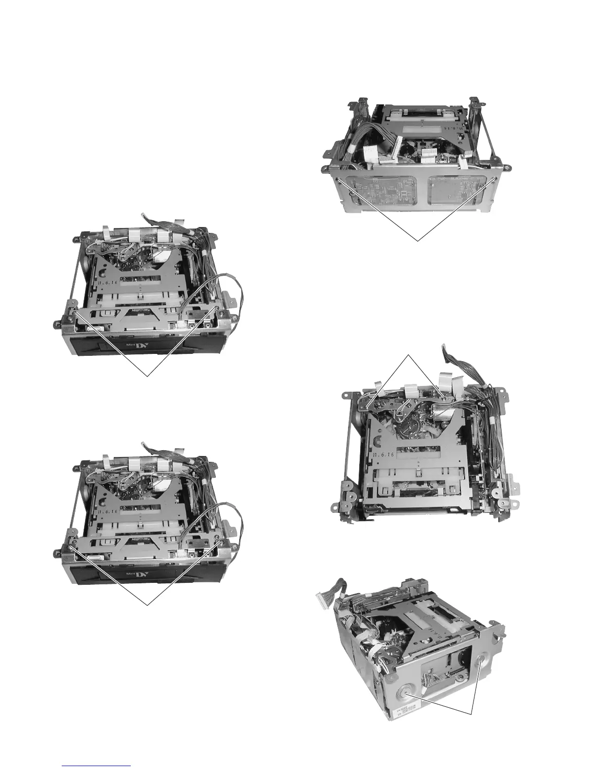
Fig. 1-7-2(1)
1.7 DISASSEMBLY OF THE VCR UNIT
The mechanism unit incorporated in the unit can be disassem-
bled as described below. Note that the following description
deals only with the method of removing the mechanism unit
from the VCR unit.
1.7.1 Disassembling the Front Part of the Unit
(1) Remove the VCR unit from the camera (see section 1.6.2).
(2) Remove the DV MAIN board (see section 1.6.3).
(3) Remove the 2 screws
1
and remove the stay on the front
cover. The cover of the cassette insertion slot will come out
together with it.
Fig. 1-7-1(1)
(4) Remove the 2 screws
2
and remove the front stay.
Fig. 1-7-1(2)
1.7.2 Disassembling the Rear Part of the Unit
(1) Remove the 2 screws
3
and remove the rear side stay.
Fig. 1-7-2(2)
(2) Remove the 2 screws
4
and remove the active head cleaner.
During this operation, be careful not to apply excessive force
to the wire that is connected between the active head cleaner
assembly and CN609 on the PR & MDA boards.
(3) Remove the 2 screws
5
and remove the side stays.
Fig. 1-7-2(3)
1
2
5

 Loading...


